The Board outline objects define the routing and scoring processes for the board. The simplest case is four lines defining the perimeter of a rectangular board. However, many PCBs have much more complex geometry. Every product must have one (and only one) outer contour. Additional outline objects may define large openings in the board, slots, scoring lines for breaking up a panel after assembly, etc.
There are four types of outline objects:
• Outer contours are closed paths (no openings or overlap between segments) describing the outer boundary of a board. When manufactured, the cutting tool will cut on the outside of the line. Inside corners in the contour will have a radius of half the tool size.
• Inner contours are closed paths (no openings or overlap between segments) describing the boundary of an opening in a board. When manufactured, the cutting tool will cut on the inside of the line. Inside corners in the contour will have a radius of half the tool size.
• Track contours are slots in the board. The center of the cutting tool follows the line, and the slot width is the tool size.
• Scoring is a process where a pair of circular blades cut into the top and bottom of the board, so that the board may be broken at a later point in time (usually after components have been mounted). Scoring lines must be straight horizontal or vertical lines which extend to the entire height or width of the board.
To create an outline object:
- Choose a cutter diameter. If necessary, enter a diameter (in mm) between 0.6 and 3.1.
Note: For flex boards, it is also possible to choose Laser as a cutter diameter. - Check off for plated edges (if desired). The outer contour of a product can not be plated.
- Select the segments from the active layer.
- Select/specify the routing depth (applies only to inner and track objects).
- Click on the button for the desired outline object.
If the selected segments do not describe a closed path, then the Outer and Inner buttons will be disabled. In the same manner, if the selected segments include anything but straight horizontal or vertical lines, then the Scoring button will be disabled.
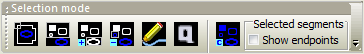
The icon buttons at the top determine how segments are selected or created. The first four buttons set the segment selection mode:
- Select chain selects all segments in a path. A path is defined as a sequence of segments where the start point of each segment is equal to the end point of the previous segment. For a closed path, you only need to select any part of the path. For an open path, you should select the beginning of the path. Previously selected segments will be deselected.
- Select selects all of the segments within the selection rectangle. Any previously selected segments will be deselected.
- Selection add selects all of the segments within the selection rectangle without deselecting any previously selected segments.
- Selection subtract deselects only the segments within the selection rectangle, leaving the remaining segments selected.
Use the left mouse button to draw a selection rectangle around the segments to select. Only segments on the Active layer (shown in blue) are selected. To change the active layer, choose a layer from the Active layer drop down list at the top of the Contour pane.
Note: Normally, only lines and arcs may be selected as contour objects. In order to select a round, oval, square, rectangle or rounded rectangle as a contour object, press the Ctrl key while selecting.
The next two buttons may be used to draw segments:
- Draw contour segment allows you to draw a contour segment manually. A straight line segment is created from the point where you press the left mouse button to the point where the mouse button is released.
- Quick contour allows you to draw a contour rectangle manually. Four straight line segments are created from the selection rectangle.
Drawn segments are used in the same manner as selected segments when creating a contour object.
Note: The two drawing modes may be useful if you have difficulties defining an outer contour, or if you simply want to do a quick import for the purpose of getting a price estimate.
The rightmost button clears all selected segments:
- Selection clear deselects all selected segments.
To delete contour objects, right click on the object and choose Delete or Delete all.