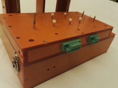
Test fixture improvementsFixture specificationWhen creating a test fixture, you may choose a fixture suitable for one of the Macaos test jigs, or specify your own dimensions.
Macaos test jigs are supplied with a generic upper fixture allowing for flexible placement of press pins. In case of more specific needs, an upper fixture may be designed by selecting the lower fixture and then opening the test fixture designer. Text may be placed on the fixture as desired. Text may be rotated in 90° increments. When a box-style fixture is designed, then connector openings may be placed in the box walls as desired. Choose from pre-defined connector sizes, or specify your own opening. Connectors may be deleted by right-clicking on the list of connectors. Pin placementWhen placing pins you may choose a Macaos pin style, or specify your own hole diameter. Test pins must be placed on pads or holes. Guide pins must be placed on holes. Press pins and support pins may be placed at any location. When placing test pins, if more than one pad/hole is selected, the pin will be placed at the center of the selected pads/holes.
|
Import module improvementsContour specificationDepth routing: When specifying inner contours or track routing, a routing depth from the top or bottom side of the board may be specified. Quick contour selection: Press the "Q" selection button to create a contour object from a selection rectangle. This is a quick way to define a rectangular outer contour in cases where only corner marks have been provided. Select pads: Pads may be selected to define slots by holding down the Ctrl key while selecting. It is not possible to select pads and lines in the same operation. Ferrite layersFerrite Top and Ferrite Bottom have been defined for use with sheets of ferrite material to be added to a PCB. Proteus link filterAn additional link filter has been added for use with newer versions of Proteus. |
Stencil module improvementsAdjust stencil opening size by height and/or widthOpenings may be adjusted by a percentage of their height and/or width (instead of or in addition to adjusting them by a percentage of their area). Stencil typesA number of additional stencil types (for licensed frame patterns, etc) have been added. Stencil optionsOptions for polished hole walls, coating of hole walls and protecting/strengthening stencil edges have been added. |
Viewer improvementsA status bar at the bottom of the product viewer indicates if the view has been rotated or mirrored.
|
Pro version improvementsThe visual appearance of the quotation module has been changed somewhat. Check boxes for quantities and lead times have been moved to the left and top edges of the price grid. An expanded price engine allows for more flexible calculation of prices for a wider variety of product parameters. Improved support for exchange rates and holidays. Panel drawings may be included with quotations. |

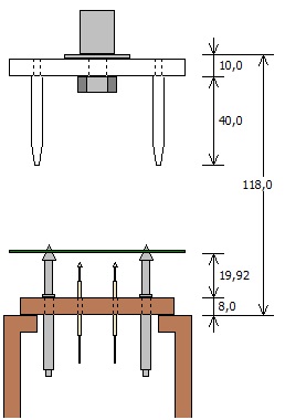
 The fixture designer supports two kinds of lower fixtures:
 Z-axis visualizer