Assembly Data Manager
The new Assembly Data Manager Module allows you to work with component purchasing and placement data for a PCB. You may also create and modify graphical remarks for a product.
Pick and Place Data (PnP)
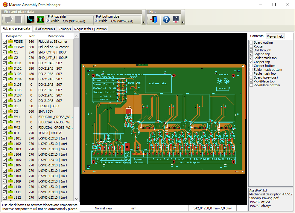
PnP data specifies the designator, location and rotation of components that will be automatically placed for (usually) reflow solderinig. There are, unfortunately, a multitude of different PnP data formats. Macaos Enterprise is able to read more than a dozen of these formats. (See the user manual for details about the most common formats supported.)
With the Assembly Data Manager, you can do the following:
- View PnP data for top and/or bottom side
- Show/hide individual components. Hidden components are deleted from PnP data once the data is saved.
- Double-click on a component in the list to zoom into that component in the viewer.
- Import PnP data
- Align PnP data. If the PnP data does not have the same coordinate origin as the Gerber data, this can be corrected.
- Create PnP data. You can select one or more pads and define a PnP component or fiducial mark to be located at the center of the rectangle surrounding the selected pads.
- Edit PnP data. You can edit the designator, side, rotation and description text for any component.
Bill of Materials (BOM)
A BOM is a list of the components that are to be used with the printed circuit board. The BOM is used to select and purchase the correct components as well as to specify where each component should be placed on the printed circuit board.
In many cases, a BOM contains component descriptions that require some interpretation by the purchaser, due to inconsistent or incomplete specifications. The Assembly Data Manager attempts to improve the usability of the BOM by applying a number of parameter recognition techniques.
The procedure is as follows:
- Import a BOM. BOM data may be imported as a text file, an Excel .xls file, or copied and pasted directly from a spreadsheet program.
- Right-click on a row to mark it as the column headers or the first row of valid component data.
- Right-click on a column header to specify the type of information contained in the column
- Click on the Process (gears) button to process the list of components.
- A new spreadsheet is created with the interpreted parameters. If necessary, make corrections and click on the Retry button to do a new search.
- Once you are satisfied with the BOM, save the processed list to the product.
- The processed list may be exported to an Excel file.
Graphical remarks
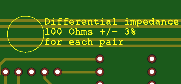
Graphical remarks may be added to any product. Existing graphical remarks may be deleted or replaced, if desired.
A remark may be created as follows:
- Click on the Add remarks to board (yellow note) button.
- Draw a circle around the feature(s) to which the remark applies.
- Enter the remark text in the dialog box.
- Click OK.
To delete a remark, click on the Delete button and draw a selection rectangle around the entire remark.
If you need to change the text of a remark, you can click on the Edit button and change a single line of text at a time. Note: This can only be done with remarks created during the current session. For older remarks, you must delete and re-create the remark.
Stencil improvements
Split/replace openings
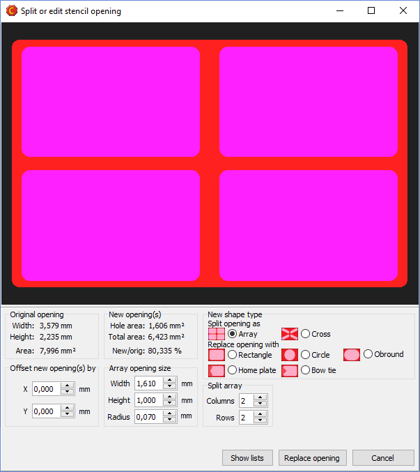
The module for splitting a large stencil opening into an array of smaller openings has been improved. It is now possible to choose between several split patterns or replacement opening shapes. You have full control over the size and shape of the new opening(s), as well as statistics to indicate how the change will affect total solder delivery.
Although this feature is primarily intended for working with large (heat sink) openings, it may be used to modify the shape of any opening in the stencil.
Highlight large pads
This feature allows you to easily locate stencil openings whose height and width are larger than the size you specify. This way you can quickly find opening that should be split.
Place board data relative to frame edge or frame center
It is now possible to specify the position of the board relative to the edge of the stencil frame, or relative to the center of the frame. Top and bottom side data may be offset horizontally or vertically, as desired.
Mirror bottom side data
Bottom side data is automatically mirrored, so that the squeegee side of the stencil will always be the top side of the stencil.
Import module improvements
Support for up to 30 copper layers
Macaos Enterprise now supports boards with up to 30 copper layers. This is an increase from the previous limit of 22 copper layers.
Full support for the latest Extended Gerber format (Gerber X2 rev J3)
A new version of the Extended Gerber file format was released in the spring of 2014. This version adds a structure for identifying the file format version, board layer or function of the file, and classes of features within the file. Macaos Enterprise fully supports reading and interpreting these extensions.
Support for Pick and Place files generated by Cadstar
Pick and place files generated by Cadstar may now be imported, either in the Import Module or in the Assembly Data Manager.
Panelization improvements
Place tabs in line
When placing break-off tabs on a panel, if you click and drag the mouse then a horizontal or vertical line is shown. When you release the mouse, a break-off tab will be placed at each point where the line crosses a board edge.
Panel drawing improvements
A table in the upper left corner of the panel drawing specifies the size of fiducials and bad marks. For a single-product panel, this table also specifies the X and Y step distance of the boards in the panel.
Product Browser improvements
Specify filenames when exporting to Gerber
When exporting a product to Gerber files for manufacture, you may choose one of two Macaos filename templates, or define your own template.