Follow this procedure to generate Gerber and Drill files from Kicad 7 or 8, for import into Macaos Enterprise. (The procedure is similar for earlier versions, but not all features or options shown here were available.)
- Open the project in the PCB Editor (pcbnew).
- Use the Place|Drill/Place File Origin command to place the origin at the lower left corner of the board's bounding rectangle. (In other words, the origin should be at the X coordinate of the left edge and the Y coordinate of the bottom edge.)
- Generate Gerber files
- Choose the File|Fabrication Outputs|Gerbers (.gbr)... command.
- In the Plot dialog box, set the Plot format, General Options, and Gerber Options as shown:
Kicad 8 note: You should set a check mark for Tent vias (rather than leaving Do not tent vias unchecked). You might also want to set a checkmark for Plot footprint text.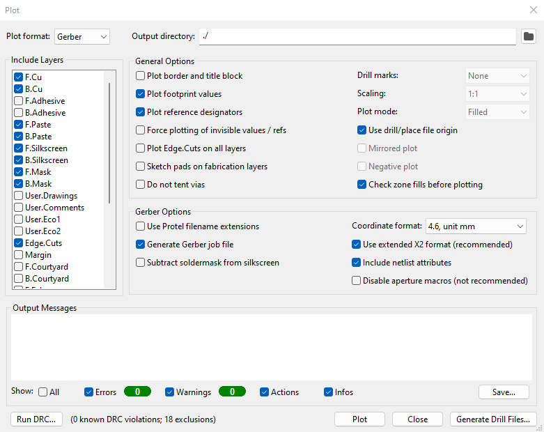
Note: If your board has less than 2 copper layers, do not set a check mark by Generate Gerber job file. The Kicad board properties dialog does not specifically support 0 or 1-layer stackups, and importing the Gerber job file will prevent you from choosing the correct stackup. - Check that all appropriate layers are selected in the Include layers list. The default selections are usually correct.
- Click on the Plot button to generate the Gerber files.
- Generate drill files
- Click on the Generate Drill Files... button to open the Generate Drill Files dialog box.
- Set the Drill File Format, Drill Origin, and Zeros Format as shown:
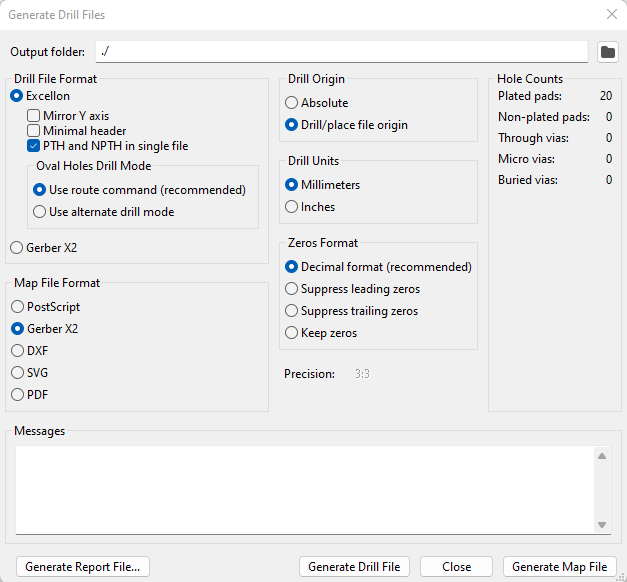
- Click on the Generate Drill File button to generate the drill file(s). It is not necessary to generate a map file or a report file.
- Click on the Close button to close the Generate Drill Files dialog box, and again on the Close button to close the Plot dialog box.
- Generate component placement data
In addition to component positions (Pick and Place data), the component layers include key pin positions and component outlines. This information is used in the Macaos Enterprise Assembly Data Manager (ADM) module, as well as to generate assembly drawings for fabrication.- Choose the File|Fabrication Outputs|Component Placement (.pos)... command.
- Set the Format and other options as shown:
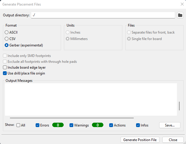
- Click on the Generate Position File button to generate the component layer(s), and then the Close button to close the dialog box.
- Generate test point data
Choose the File|Fabrication Outputs|IPC-D-356 Netlist File... command, and save the file. - (Optional) Generate 3D file
A 3-dimensional file, in STEP format, is a necessity when designing a test fixture for a board. We highly recommend including a STEP file.- Choose the Export|STEP... command.
- Set the Coordinates and other options as follows:
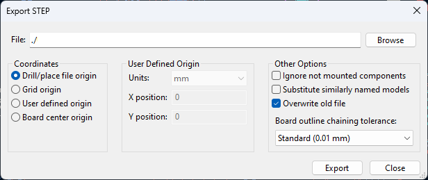
- Click on the Export button to generate the STEP file, and then the Close button to close the dialog box.
- Generate BOM data
A BOM should have as much specific, unambiguous information as possible. This helps prevent misunderstandings and leads to quicker response time for quotations and for manufacturing. Ideally, every component should have a complete manufacturer part number (MPN), even when alternates are suitable.- Open the schematic editor.
- Choose the Tools|Edit symbol fields command to open the Symbol Fields Table editor.
- You should at least have the following fields: Reference, Value, Footprint, Manufacturer, and MPN. More fields may also be added, such as Mount [TH,SMD], DNP (do not place), or Additional Info.
- Remove the check mark from Group symbols
- Fill in empty cells, as necessary.
- Click on the Export as CSV button, and save the file.
- Pack all of the files generated in steps 3-8 in a zip file (e.g. Send to|Compressed (zipped) folder in Windows Explorer).
- Open the zip file in Macaos Enterprise Import.
- The Gerber files should automatically link.
- Link the drill file(s) to the appropriate drill depths.
- Link the [projectname]-pnp-top.gbr file to the Additional Layers|Component Top layer, and the [projectname]-pnp-bottom.gbr file (if any) to the Additional Layers|Component Bottom layer.
- Link the [projectname].d356 file to IPC-D-356 Netlist.
- Link the [projectname].csv file to Parts List (BOM).
- Check the stackup, surface finish, mask colors, and product identification, and modify as necessary.
Note: If you have suggestions for updating this information, please send them to us at support@macaos.com.