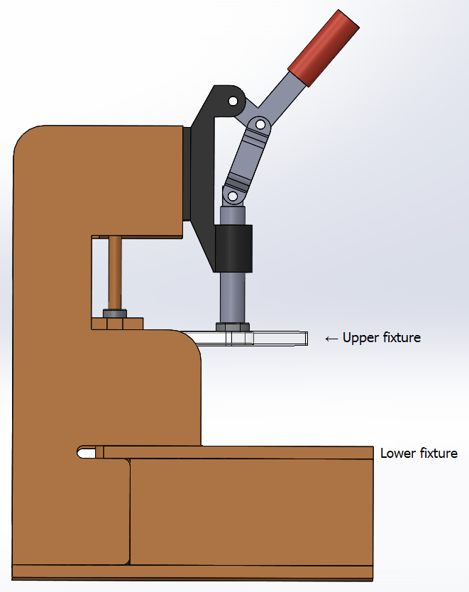
 A test jig is an apparatus into which a printed circuit board assembly (PCBA) may be inserted, so that appropriate contacts may be made for in-circuit testing. Typically, the test jig holds the PCBA between an upper and lower test fixture. When the two fixtures are pressed together, ;spring-loaded test pins make contact with test points on the PCBA, thereby allowing test circuitry to perform an in-circuit test of the PCBA.
The Test Fixture Designer module supports designing fixtures for three different generations of test jigs: The Macaos Integrated Test Jig, the Macaos Box Jig, or a legacy jig. You will find the Box and Legacy jigs, as well as a variety of test pins, cables and other accessories, available for purchase from the Global products|Test accessories folder in the Macaos Enterprise Product Browser.
The Test Fixture Designer module imports test pin locations, if they are included in the component layer of the PCBA to be tested.
Note: Do not confuse test points with test pins or test pads.
-
Test pads are the locations for bare-board testing of the PCB during manufacture, which are extracted from an IPC-D-356 file to the Test pads layers.
-
Test points are specific pads or pins on the PCBA which would be used for in-circuit testing. For each test point, a “component” (with the Test point component class) should be added to the appropriate component layer. Ideally, test points (with TPxx designators) should be included in Pick and Place data, but they may also be created manually.
-
Test pins are the pins in a test fixture which will make contact with the PCBA during in-circuit testing.