Create wave solder pallets
With this new module, you can quickly design a pallet for transporting a board or panel through a solder wave. Solder pallets are useful when working with small, thin or irregular boards, as well as with boards that have both PTH components and solder-side SMT components.

Two styles of pallets are supported:
- A wave solder pallet exposes the entire board to the solder wave.
- A selective wave solder pallet exposes only specified regions of the board to the solder wave.
Creating a selective wave solder pallet is easy:
- Select a material and thickness and specify component pocket depths.
- Place board fasteners at desired locations around the board.
- Draw "opening" outlines around the components to be soldered.
- Draw "pocket" outlines around the solder-side components that are covered by the pallet.
- Generate a milling file for the pallet.
All other elements of the pallet are calculated automatically. This includes edge rails, bottom side bevels, pallet floor, seal walls, etc.
Creating a wave solder pallet is even easier, since steps 3 and 4 above are unnecessary.
Note: Selective wave soldering requires some planning during board layout, in order to have sufficient clearance between wave-soldered components, and components which must be shielded from the solder wave.
PCB as test fixture
The Test Fixture Designer module has been expanded to allow creating a PCB test fixture.
Rather than using a sheet of fixture material as a holder for the test pins, it may sometimes be more useful to mount the test pins directly into a PCB.
For a standard test jig, choose Lower w/ PCB. For other jigs, choose Lower - flat and set the thickness to 3.2.
Use the Gerber button to export the fixture outline and holes to a Gerber file, which may then be imported to your CAD system for further design.
Import module improvements
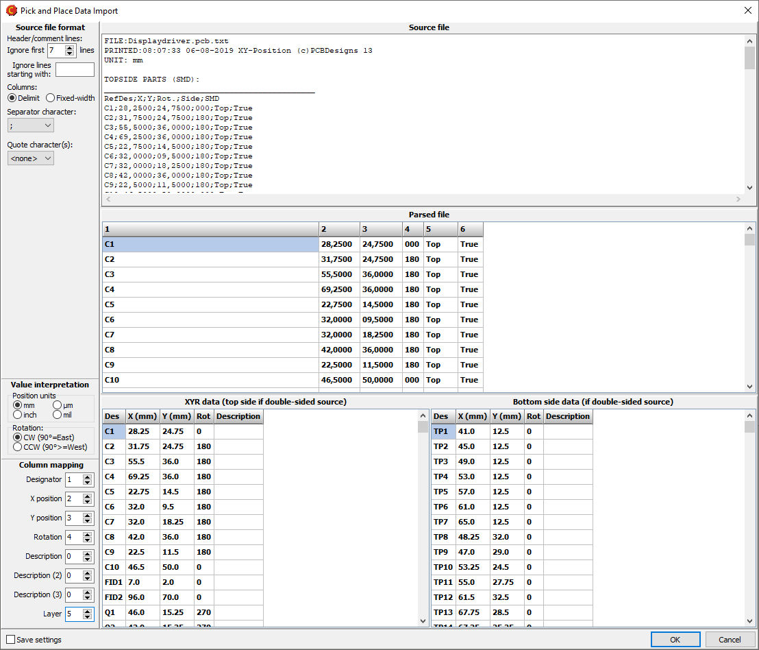
PnP format specifier dialog box

When importing a Pick and Place file, if the file format is not automatically recognized, you can specify the format as necessary.
Mark holes as press-fit
It is now possible to mark holes as press-fit. This is done by right-clicking on the appropriate tool(s) in the drill tool list, and selecting Via protection/Press-fit|Press-fit.
Laser cutter tool size for flex boards
For flex boards, it is possible to choose Laser as a cutter diameter. Note: Laser is only suitable for outer and inner contours.
Backdrill layers
Drill files may be assigned to backdrill layers.
Other improvements
New button bars in product browser
![]() A button bar above the folder list gives quick access to commonly used folders.
A button bar above the folder list gives quick access to commonly used folders.
![]() A button bar at the bottom of the product list gives quick access to commonly used product operations (found in the right-click menu).
A button bar at the bottom of the product list gives quick access to commonly used product operations (found in the right-click menu).
View list of active RFQs
Use the Operations|Active RFQs menu command to display a list of your active RFQs (if any). An RFQ may be created if you don't get an online price for a product.
Right-click on an RFQ and choose Cancel RFQ to cancel it.
Request interactive support
If you need help, an Elprint engineer can provide you with interactive support. Elprint uses TeamViewer technology, which allows the engineer to see your desktop and help you to quickly resolve your issue.
Click on the Interactive support button, which displays instructions for setting up a support session.
Note: Interactive support is only available for Elprint customers.
