Macaos Enterprise
Macaos Enterprise
Macaos Enterprise is a cloud-based system for working with printed circuit boards in real world applications and simplifying your PCB acquisition process. Whether you are part of a large organization or just a service provider in the supply chain, Macaos Enterprise will help you get the job done.
Macaos Enterprise is not a design tool for PCBs. There are many good tools available for designing a single PCB. However, most such tools stop there. You get an excellent PCB design converted to an output format (such as Gerber and drill files) which may then be sent to a fabricator.
However, a single bare printed circuit board is not a finished product. Modern electronics manufacturing makes use of automated assembly lines for component placement, soldering, depanelization, test and more. The various modules in Macaos Enterprise allow you to rapidly generate the data and tooling necessary for these assembly steps. Macaos Enterprise also eases the process of purchasing PCBs.
Macaos Enterprise is available for free download.
Macaos Enterprise includes the following tools and modules:
- Product Browser
View and organize your products. The graphic viewer allows you to view, inspect and measure any detail in the product. The browser also lists key product specifications, fabrication history and order history. - Import
Import a PCB product from Gerber/Drill or ODB++ data (and Pick&Place data if available). Select or define stackup, specify mask colors and other parameters, and then publish to the Product Browser. - Panel
Step up a PCB board to an array (panel) suitable for assembly in a matter of seconds. Place break-off tabs automatically, or exactly as you wish. Add fiducial marks, tooling holes, bad marks, copper fill, bar codes, text, and test coupons to the panel frame. - Solder Paste Stencil
Create a solder paste stencil product, from an existing PCB product or a gerber file. Choose a stencil frame or upload your own. Specify adjustments to pad openings, split or modify the shape of openings, define stepped (thinner) regions, add text and more. - Assembly Mask
Add assembly mask data (such as peel-off, glue or solder paste) to an existing PCB or panel without needing to go back to the original CAD Layout system. - Assembly Data
Add or edit the Pick and Place (PnP) and Bill of Materials (BOM) data for a PCB. Send a Request for Quotation (RFQ) to participating Electronics Manufacturing Service (EMS) providers. - Pallet creation
Design a wave solder pallet or selective wave solder pallet. You only need to define pallet dimensions and parameters and place board fasteners. For a selective wave solder pallet simply draw the solder openings and component pockets. The rest is calculated automatically. - Depanelization
Generate a milling file (in G-code) for removing break-off tabs from a panel. Design a fixture to hold all boards in place during tab removal. - Test fixture
Design a "Bed of Nails" test fixture for a PCB. Click on holes or pads to place guide pins or test pins. Test jigs and test pins for a complete in-circuit test setup are available for purchase from the Test accessories folder. - Online Prices and Ordering
Instant online quotations are available for most products. Select a price and add to the shopping basket to place an order. - Technical Documentation
Generate technical drawings in PDF format. - Mechanical Parts
Upload a 3D object and purchase it in plastic or aluminum. - Connectors, Accessories and Machines
Purchase connectors, test jigs and accessories, ESD accessories, stencil stretching frames, milling machines, laser engraving machines, and more. - Collaboration (Product Sharing)
The product sharing features of Macaos Enterprise allow a board owner to share the board with an EMS supplier. The EMS supplier can then panelize the board, add assembly mask data, and create solder paste stencils optimized for their own assembly processes, either for quotation purposes or to place an order for production.
We are constantly working to improve and expand Macaos Enterprise. Expanded component management, transport pallet designer, laser engraving of serial numbers, and output to solder paste printers are among the features we have under development. Your input to our development process is welcome. You can contact us at support@macaos.com
More info:
Product Browser
Product Browser
With Macaos Enterprise you can easily manage information about your PCBs and related products. Product information, production data, order and fabrication history, etc. is at your fingertips.
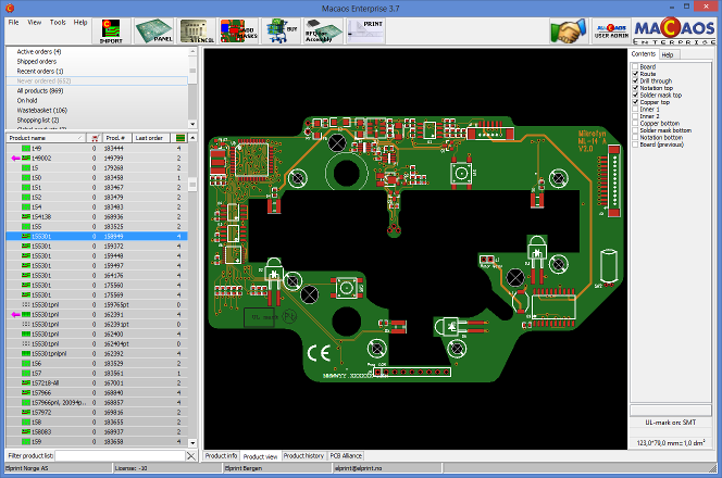
The Product Browser allows you to browse all of your products for product specifications, fabrication history, order history, etc. Products may be sorted into customizable project folders for easy searching. You can also put products "on hold" to temporarily disable them. A Recent Activity list lets you quickly find your company's most recent quotations, orders, shipments and more.
The Product Viewer allows you to view and inspect the product's Gerber, drill and pick & place data in detail. Features include pan, zoom, measure and complete layer selection. Documentation files, including automatically generated stackup drawings and panel drawings, may be viewed or saved locally. You may also add additional documentation to the product, if necessary.
The print utility may be used to generate high quality technical drawings in PDF format. Layout drawings for each layer, stackup drawings and drill template drawings may be generated.
More info
Import
Import
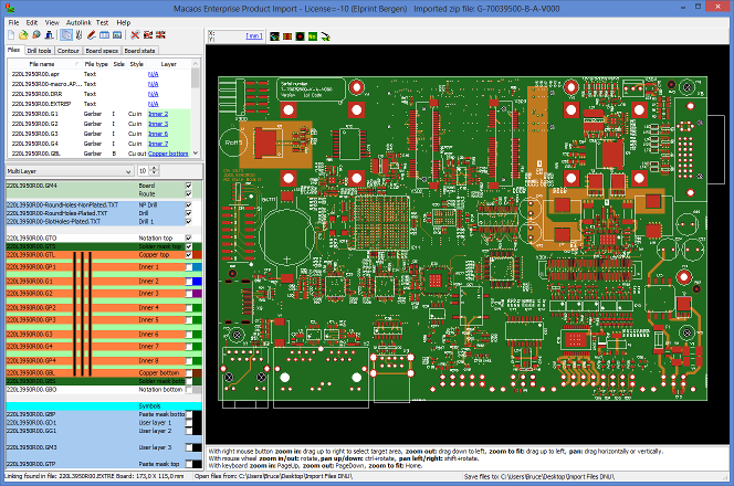 The Import Module is used to read Gerber or ODB++ data, as well as pick & place data and documentation, into the system and "package" the data into a PCB product. Each input file is automatically mapped to it's board layer, based on an AI-based filename analysis or by using pre-defined or customizable filename filters. A WYSIWYG viewer shows your board just as it will be interpreted by the manufacturer. Once the PCB has been "published" to the system it will appear in the Product Browser, ready for panelization and/or purchase.
The following data formats are supported:
- Gerber (from the current version to most legacy versions)
- Drill (XNC, Excellon, Sieb&Meyer, most NC Drill formats)
- Rout (XNC, Excellon, Sieb&Meyer)
- ODB++ (most versions, except XML-based)
- Pick and Place (most ECAD-generated formats)
- DXF (limited support, for documentation purposes)
- HP-GL (limited support, for documentation purposes)
Stackups
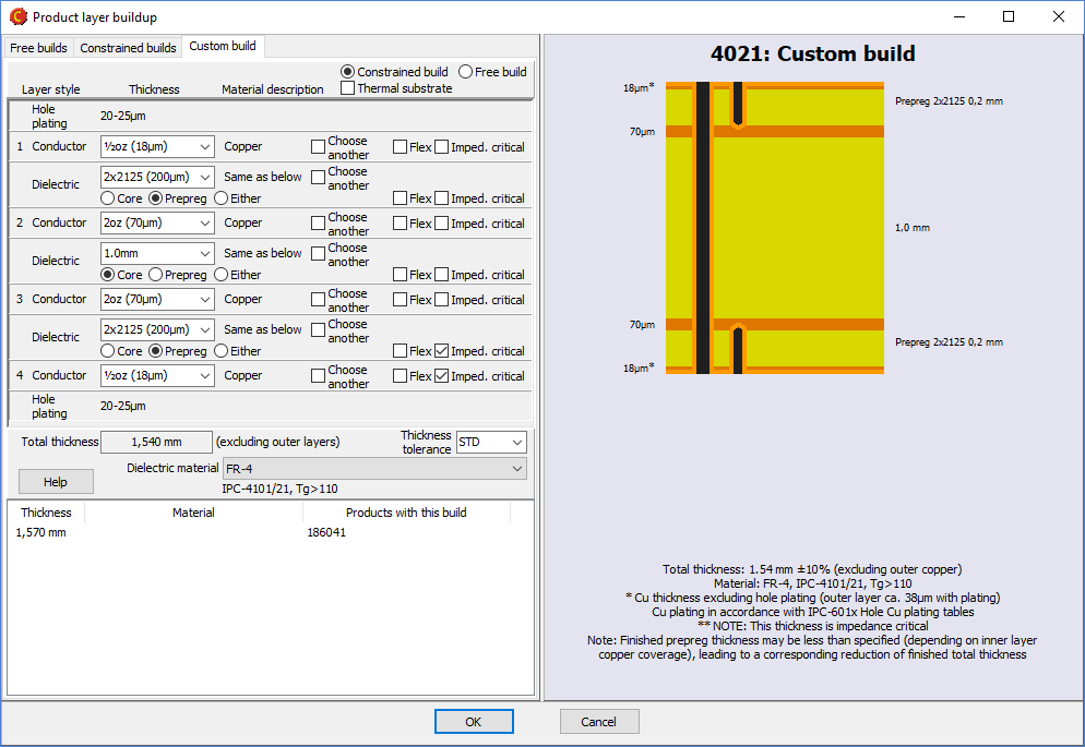 When defining your board, you may choose from a large selection of pre-defined stackups, or define your own buildup. Either way, a high quality technical drawing of the stackup is automatically generated in PDF format.
The custom stackup editor supports flexible, flex-rigid and metal-based stackups. The most common material types (defined by IPC-4xxx slash sheets) are available for selection. If desired, you may query the CircuitData materials database when specifying dielectric materials for special needs. Your previously used stackups are also listed for re-use.
Symbols
 A unique feature of the import module is the ability to add symbols or fiducial marks to the component legend or solder mask layers. Available symbols include: Lead-free, CE-mark, WEEE, Recycle, ESD, RoHS, text, bar code, fiducial and the fabricator's UL-mark.
There is also a function to generate an IPC/JEDEC J-STD-609A compliant text string specifying the materials used in the PCB.
More info
Panel
Panel
Macaos has developed an intuitive, yet flexible, rapid PCB panelizer tool.
Assembly arrays/panels
The Panelizer Module allows you to quickly step up a PCB board to an array (panel) suitable for assembly. The panel may be generated automatically from a script or you may specify panel parameters and add features to the panel frame as desired. Downloadable scripts from EMS providers may be used or modified to meet your own needs.
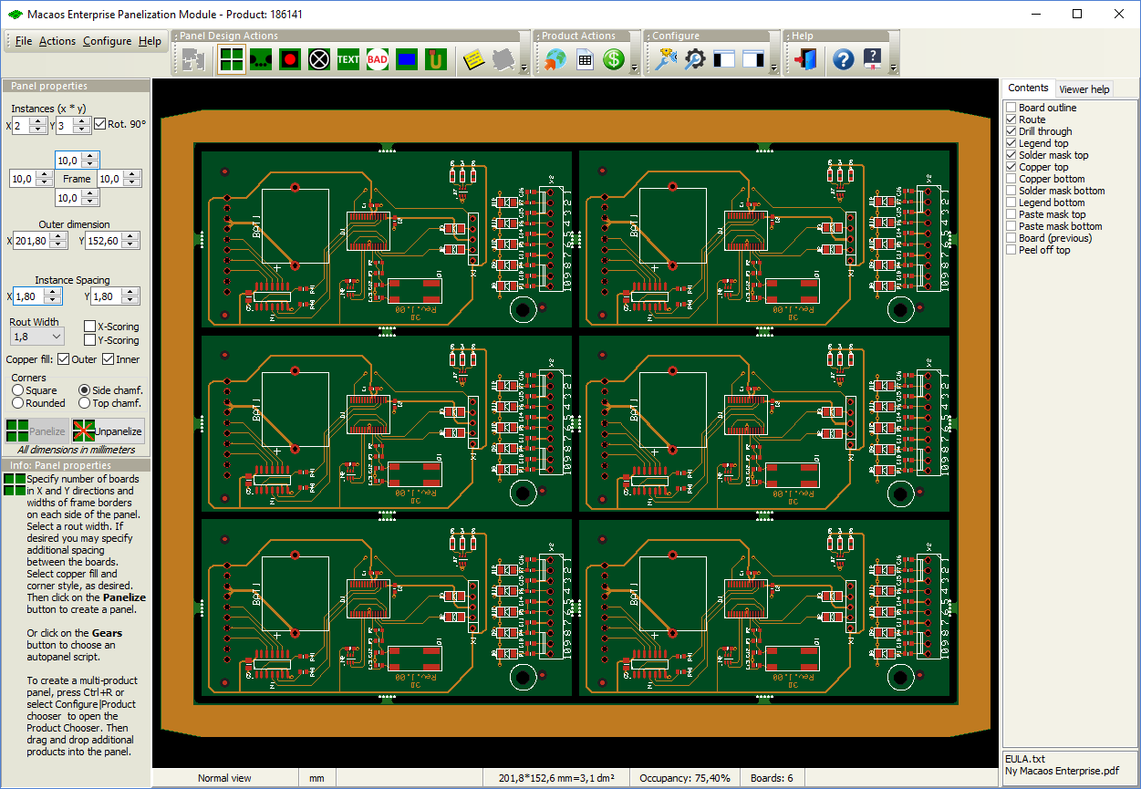
You can easily add features to the panel, such as:
- Break-off tabs: corner tabs or edge tabs with or without mousebite holes
- Fiducial marks: round, square or cross, placed relative to panel or board corners or centers
- Tooling holes or slots, placed relative to panel corners or center
- Break-off holes
- Bad marks
- Copper fill in frame and between boards
- Text
- Bar code, Code 128B or Datamatrix
- Annotation field
- Peel-off, glue or other assembly mask data
- Registration control coupon
- Impedance test coupon (IPC-2221B type Z)
- Any small board as a coupon
Most of these features may be specified in a panel script, so that they are automatically added to any panel that you create using that script.
A WYSIWYG viewer shows your panel just as it will be interpreted by the manufacturer. A high-quality technical drawing of the panel in PDF format is automatically generated when the panel is saved.
Pick and place data (if included in the board product) is stepped together with the boards.
Multi-product panels
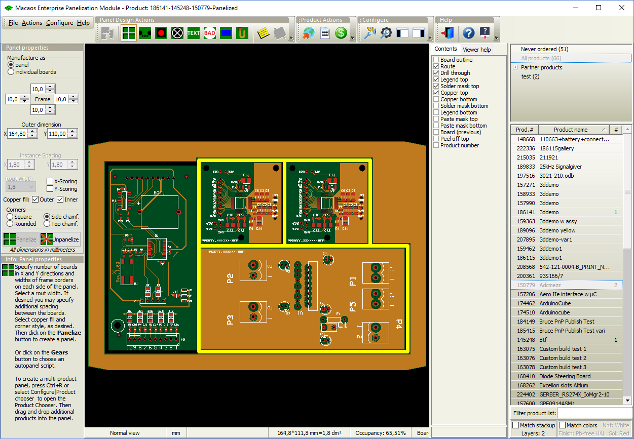
Panels that combine several different products are also supported. Start by selecting a single product in the product browser and open the panelization module.
Open the product chooser with the Configure|Product chooser command. The product chooser lists all products that are compatible (stackup, finish, mask colors) with the first product. You may then add products to the panel by dragging them into the panel.A multi-product panel may be delivered either as a panel or as individual boards. If individual boards is selected then there will be no panel frame or break-off tabs.
More info
Solder Paste Stencil
Solder Paste Stencil
The Stencil Product Creator Module allows you to quickly define a solder paste stencil for your PCB.
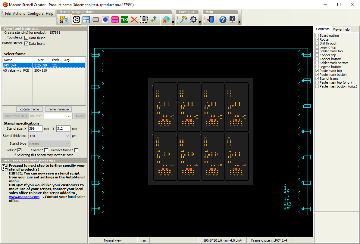
Using the copper layer and paste mask layer data from the PCB, you can do the following:
- Select a frame from among pre-defined or uploaded frame data
- Adjust all opening sizes by a percentage of area
- Adjust the corner rounding of all openings
- Fine tune individual opening sizes to correct for process issues
- Mark fiducials for etching (rather than cutting)
- Add text
- Place top and bottom openings side by side on the same stencil
- Split a large opening into an array of smaller openings
- Define regions of the stencil to be built up or etched down to a different thickness
All opening size adjustments are defined as a percentage of the copper pad area (when copper data is available). The WYSIWYG viewer lets you see how your adjusted openings compare to the copper pads.
A frame manager and editor allows you to upload frames or build new frames based on pre-defined templates. Frames may be defined with variable texts (company name, product number, etc) which automatically get substituted in the Stencil Product Creator.
Once a stencil product has been published, you can get prices and order the stencil in the same manner as for PCB products.
More info
Assembly Masks
Assembly Masks
Frequently, the necessary data for assembly masks is missing from the Gerber files created by the board designer. Especially in cases where assembly is being done by an EMS provider, this missing data can be a problem. It is the EMS provider who knows the processes and needs to specify the masks, but getting this information to the board designer early enough to be included in the design is usually not possible.
With this feature, mask areas may be specified by the production engineer from within Macaos Enterprise. Mask areas may be specified either to fill a rectangle drawn by the user, or to fill all solder mask openings within a rectangle drawn by the user. The following masks may be defined:
- Peel-off mask (Blue mask)
- Paste mask
- Glue mask
- Hard gold
- Carbon
- Kapton tape
- Legend
- Solder mask
By adding paste mask data to the desired solder mask openings of a panel, it is possible to create a solder paste stencil when paste mask data was missing at the time the product was created. Although the solder mask openings are usually somewhat larger than the copper pads, this is easily corrected in the Stencil module, which adjusts openings relative to the original copper pad size (when available) rather than the specified paste mask pad size.
More info
Assembly Data Manager (ADM)
Assembly Data Manager (ADM)
The Assembly Data Manager (ADM) is an integrated BOM Tool and Pick and Place Data Manager for PCBs. It provides an environment for managing and reviewing Pick and Place (PnP) and Bill of Materials (BOM) data.
An integrated, standards-based solution
The ADM helps dramatically reduce time and effort in preparing assembly data, by combining the following features in a single module:
- Graphic viewer with component editing functionality
- Structured component overview with properties editor
- Component search facility
- Send RFQ for assembly to participating EMS providers (Basic version only)
- Component price estimator (Pro version only)
- Component rotation, height and solder temperature editor
- Export PnP and BOM data (Pro version only)
The ADM makes use of the recently released X3 extensions1 to the Gerber Format to combine PnP, BOM and Assembly Drawing data into an integrated component layer of a PCB product. As CAD systems2 implement these extensions, a rapid and error-resistant path from designer to manufacturer may be achieved.
The component layer displays the location, rotation, size and key pin location of each component together with properties such as manufacturer part number, supplier SKUs, height, max solder temperature, etc. The use of a standards-based structure for this information allows purchasers, supplers, process line operators, etc to automate their systems and thereby reduce costs.
1 Macaos actively participates in the development of these standards.
2 Some CAD systems, such as kicad, already support Gerber X3 output.
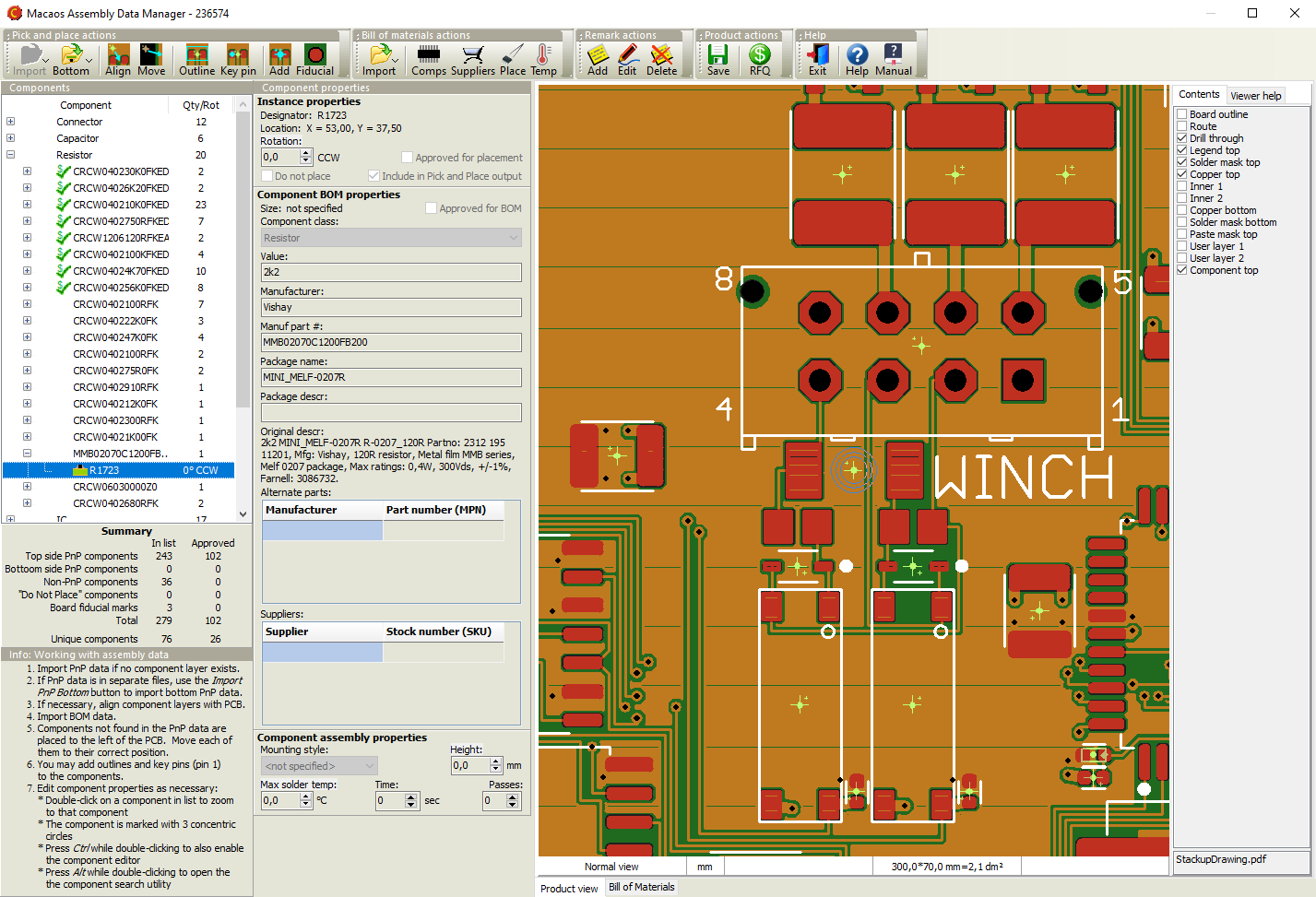 An efficient and straightforward workflow
- Import PnP data. (This may already have been done when the PCB product was imported.) This should be done prior to importing BOM data.
- If necessary, align the PnP data with the PCB data.
- Import BOM data. (This may already have been done when the PCB product was imported.)
- If necessary, move new components to their correct position. BOM components are matched to PnP components by their designators. BOM components which are not found in the PnP data are placed to the left of the PCB. Each of these should be moved to its correct position on the PCB.
- Draw outlines and mark Key Pins. For assembly purposes, it is desirable to graphically display the size and orientation of each component. This information is typically not included in the imported PnP or BOM data, but it can easily be added by drawing outlines and marking key (1 or A1) pins.
- Check/edit the properties of each component. Ideally, a complete manufacturer part number should be specified for each component. At the minimum, each component description should be unambiguous. The edit module includes an online component search function (powered by Octopart) to aid in quickly specifying unambiguous manufacturer part numbers.
- Save changes to the product and generate reports as desired.
Request a quotation for assembly
Once the BOM list is complete, Macaos Enterprise users can send an RFQ for assembly to participating EMS providers. This makes the PCB data and assembly data visible in the EMS provider's Macaos Enterprise so that they can prepare their quotation without you needing send data by unsecure means (such as e-mail).
For more info about becoming an EMS provider listed in this module, click here.
More info
Solder Pallets
Solder Pallets
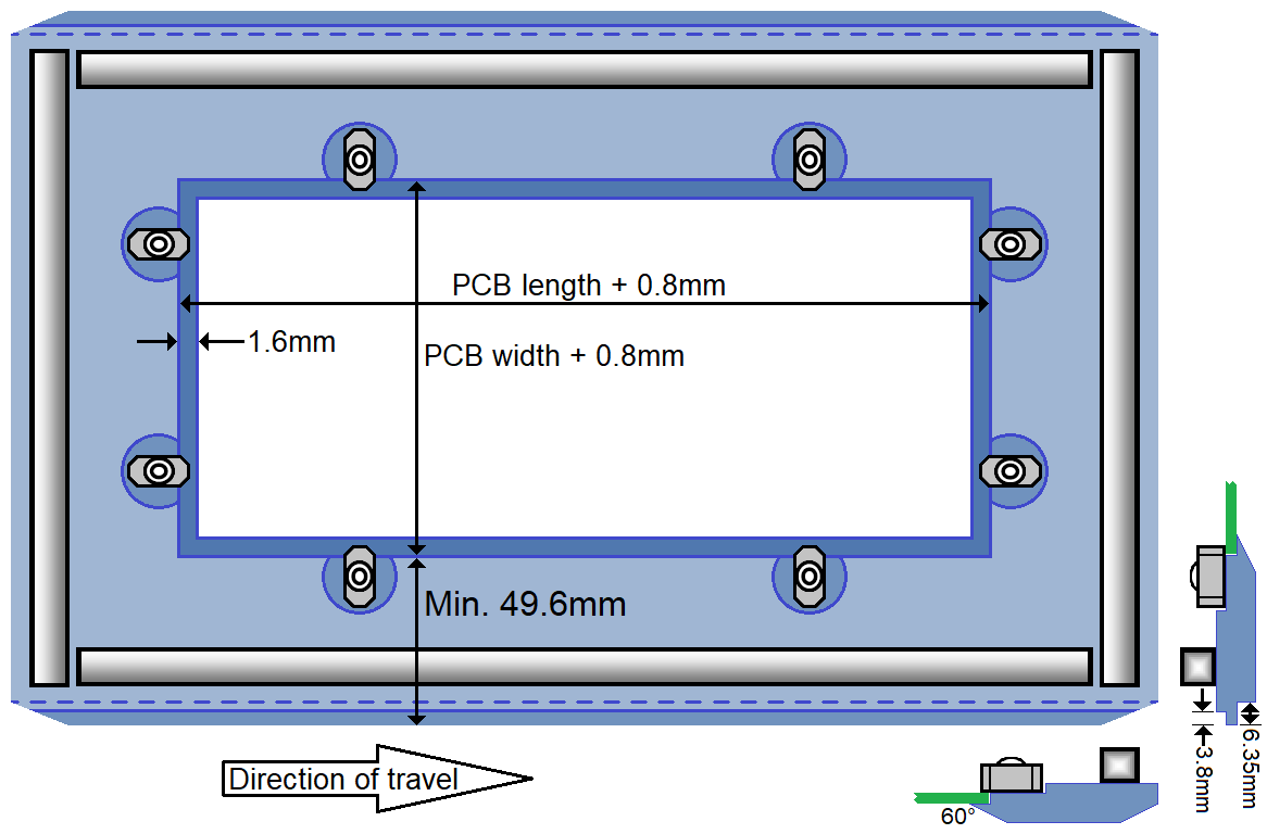
A wave solder pallet is a reliable and inexpensive fixture for soldering through-hole components. The pallet is typically made from a synthetic material, such as Durapol or Durostone®. Macaos supports the design of both full and selective wave solder pallets.
The Macaos Pallet Creation module allows you to easily and quickly design the following types of pallets:
-
A wave solder pallet exposes the entire solder side of the PCB to the solder wave. For panels, there is an opening for each board in the panel. This would typically be used to support small, thin or irregularly shaped PCBs as they travel through the wave soldering machine.
-
A selective wave solder pallet exposes only regions with plated through-hole (PTH) components to the solder wave, while protecting other regions from the solder wave. This would typically be used when soldering PTH components on a board which also has surface-mounted (SMT) components, gold fingers, ground planes, heat-sensitive or other areas needing protection on the solder side of the PCB.
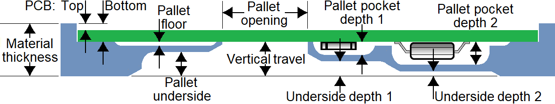
Both styles of wave solder pallets have the same frame, with stiffener/solder-dam on all four edges of the top side, and rotary PCB fasteners. The bottom edge of the rail fingers is flush with the bottom side of the PCB. The leading and trailing edges, as well as all four corners, are chamfered.
In Macaos much of the pallet design is calculated automatically. You need only define the following:
-
outer dimensions and material parameters
-
placement of PCB fasteners
-
solder wave openings (selective wave solder pallets only)
-
component pockets (selective wave solder pallets only)
More info
Depanel
Depanel
Depanelization is the process of removing individual boards from a panel, after the boards have been populated with components. Traditionally, boards have been depanelized by breaking or cutting the the break-off tabs which hold the panel together. However, the mechanical forces (particularly bending) which can take place may weaken or damage the solder joints of fine-pitch SMT components near the board edges. This problem can be mitigated by using a milling machine to remove the break-off tabs.
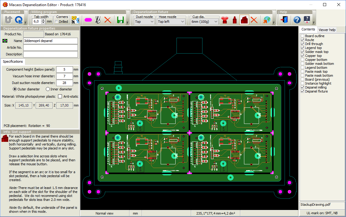
The Macaos Depanelizer module allows you to easily and quickly accomplish the two specific tasks required for depanelization by milling machine:
-
Generate a milling program for removing the break-off tabs from a panel. A milling program contains the numerical instructions for operating a CNC milling machine which removes the break-off tabs from the panel.
-
Design a fixture for holding the panel frame and boards in place during the milling process. The depanelization fixture holds the boards in place, so that they do not move or otherwise get damaged during the milling process. Macaos has developed an inexpensive and reliable fixture style for this purpose. The fixture uses registration “pedestals” and vacuum suction to hold the boards in place as they are loosened from the panel, as well as a suction nozzle to remove dust from the milling process.
More info
Test
Test
 Macaos has developed a simple and cost-effective jig for in-circuit testing. The test fixture module allows you to design a test fixture by simply clicking on the test points in your board, and assigning each pint with a pin type (and appropriate labels for a wiring list, if desired).
Test fixtures
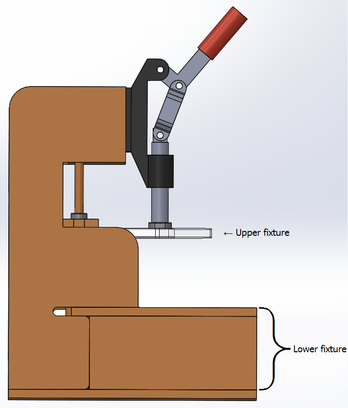
A "Bed of Nails" test fixture is a plate with an array of spring-loaded test pins (or Pogopins) which are mounted in the fixture so that they will make contact with desired test points on the PCB. In addition, a few guide pins are placed at mounting hole locations in order to properly align the PCB with the test pins. The PCB is placed on top of the pins and then pressed down so that the pins make good contact with the test points. Ideally, all test points should be accessible from the bottom side of the PCB.
The lower fixture of our standard test jig is a box with hinged top and bottom. It is delivered with holes drilled for the test pins, guide pins, connectors, etc. as specified in the test fixture module. Test pins and other accessories may be ordered together with the test jig and fixture, directly in Macaos Enterprise.
The standard jig is delivered with an upper fixture with slots that allow you to place press pins where appropriate. For boards with test points on both sides, it is possible to design an upper fixture with test pins.
Test pins
Typically, test pins consist of two parts: 1) a receptacle which is mounted in the fixture plate and wired to a connector, and 2) a spring loaded pin which is inserted into the receptacle. The spring-loaded pins are available with a variety of different pin heads, which are chosen according to the type of test point contact to be made (via hole, solder pad, component pin, etc).
More info
Online prices and ordering
Online prices and ordering
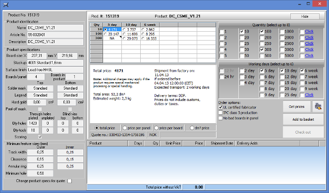 The Quotation Module gives you access to online price quotations from participating suppliers. Select multiple board quantities and delivery times in order to choose the quantity/delivery/price combination that suits your needs. Once you have selected your desired price, your order can be placed with just a few mouse clicks.
Suppliers participating in the Macaos Enterprise System have sales offices in Denmark, Norway, and Sweden, which serve customers througout the European Economic Zone and elsewhere.
Note: If you are interested in participating as a supplier or reseller, you can join the Macaos Enterprise System.
More info
Macaos Enterprise user guide: Quotations and the Shopping Basket
Technical Documentation
Technical Documentation
Macaos Enterprise can generate technical drawings in PDF format for your products. Three kinds documents can be generated. All drawings have an ISO standard title block with user-specified content.
Layout documentation set
A layout documentation set is a PDF file with several drawings, one drawing per page. The contents of the set are
- An overview of product properties
- A layout drawing for each layer in the product
- A stackup drawing (for PCB products)
- A drill template drawing for each drill layer in the product
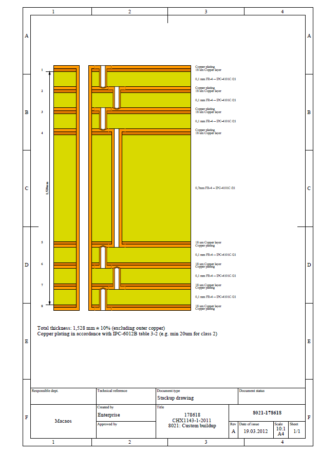
Stackup drawing
A stackup drawing shows the dimensions and materials of the copper and dielectric layers of a PCB product. It also shows the depths of through, blind and buried holes, if any.
Panel drawing
A panel drawing shows the placement of boards and frame objects in a panel.
More info
Mechanical parts
Mechanical parts
The Mechanical Part Import Module is used to import a 3D mechanical part from an STL file.
The object dimensions are displayed. If necessary, click on one of the units buttons so that the dimensions are correct. The volume, weight and total surface area of the object are also displayed.
Material properties
Select the desired material for the mechanical part. A selection of photopolymer or stereolithographic plastics are available for 3D printing. It is also possible to select aluminum (with a variety of finishes) for machining.
If a non-transparent plastic material is selected, then you may choose a paint color and finish.
Publishing
Once dimensions and properties are correct, click on the Publish button to publish the product.
When publishing the mechanical part product, you will be asked to include a STEP file with the imported product. A STEP file gives more accurate machining information than an STL file, especially if the object contains many detailed curved surfaces. For machined aluminum parts, a STEP file must be included.
Macaos Enterprise needs an STL file to display and calculate the dimensions of a mechanical part. And for simpler parts, the STL file is sufficient for manufacture. However, best results are obtained by importing both files to the product.
More info
Connectors, Accessories and Machines
Connectors, Accessories and Machines
While PCBs, stencils and test fixtures are products which may only be purchased by their owner (and partners), Macaos Enterprise also supports purchasing “ownerless” products. There are several categories of “ownerless” products:
- Global products are PCB products which may be purchased by anyone. These are typically kits for student projects.
- Connectors A wide variety of connectors styles are available, and each style has several parameter options. Use the Connector Chooser to browse and select a connector.
- ESD accessories are anti-static bags, tape, labels and related products.
- Machines are milling machines, laser engraving machines, label dispensers and more.
- Software is software licenses, maintenance agreements and related products.
- Stencil frames are stencil stretch frames and other stencil related accessories.
- Test accessories are test jigs, test pins and related products.
- Other off-the-shelf products are any off-the-shelf products not included in the preceding categories.
Off-the-shelf products may be purchased in much the same manner as PCB, stencil or fixture products.
In cases where an online price is not available, placing an order is in essence a Request for Quotation (RFQ). The sales office will get back to you with price and availability details and then await your confirmation before processing the order.
Connector chooser
The Connector Chooser is used to browse the catalog of available connectors and select a connector for purchase.
Selecting a connector family from the category tree loads its description and options, and displays a drawing and/or photograph of the connector family. You may then select the specific parameters, such as pin count or contact plating, of the desired connector. Clicking on the purchase button loads the selected connector into the Quotation module.
More info
Collaborate
Collaborate
Macaos Enterprise is designed for collaboration. You can share your products with your design bureau, fabricator, EMS, purchaser, etc so that each partner has access to the data they need without compromising product security.
For example, a product might go forward like this:
- When the design bureau finishes the board layout, they load the Gerber, drill and pick & place data, together with drawings and other documentation, into the Import Module.
- Once the product has been specified in the Import Module, the design bureau publishes the product, assigning ownership to the product's owner.
- The product owner locates the product in the Product Browser and clicks on the RFQ for Assembly button to generate RFQs for populated boards. This module automatically "shares" the product with participating EMS providers, and then asks them for a quote for a batch of populated boards. Alternatively, the product may be shared manually and any EMS provider may be directly contacted for a quotation.
- The EMS production engineer analyzes the board and adds assembly mask data (such as peel-off mask, glue mask, paste mask, etc) to the board product (or panel), as needed.
- The EMS panelizes the board as best suited to their own processes and uses the quotation module to estimate their cost for the bare boards. This, together with the product's pick & place data and BOM allows them to make a quotation.
- Once the EMS gets the order, they can order the panels and solder paste stencils via Macaos Enterprise.
- When the bare boards are finished, the fabricator uploads quality documentation and shipment tracking number, so that it is visible in the Product Browser.
- The EMS may use the Depanel module to generate a milling program for depanelization. They may also use the Test fixture module to design a test fixture for the populated boards.
- When the populated boards are finished, the EMS uploads quality documentation and shipment tracking number, so that it is visible in the Product Browser.
Macaos Enterprise has several levels of access and visibility, so that the product owner can control access to their data.
More info
Macaos Enterprise user guide: Product sharing