Linking files
Linking files BruceThe Files pane lists the files which have been added to the project using the File|Add files command. Each file is listed together with its file type and the layer to which the file has been linked. Multiple files may be selected when opening files. Additional files may be added executing the File|Add files command again.
When a file is added to the list, an attempt is made to determine the file type. If, for some reason, the file type is incorrect, it can be changed by right-clicking on the file and choosing the correct file type from the Change file type submenu. (Note: Empty image files are identified as text files.)
The contents of the file list may be filtered with the Configure menu:
- Configure|Hide linked files hides all files that have already been linked
- Configure|Hide non-image files hides all text files and other non-image files
- Configure|Hide common part of file names shows only the portion of filenames used by autolinking
Image files
Image files BruceClicking on an image file imports the file into the system (if necessary) and displays the file in the Graphic Display. Macaos Enterprise is able to import the following image file formats:
- Basic Gerber (RS-274D)
- Gerber (RS-274X Extended Gerber)
- NC Drill (XNC, Excellon or similar; drill only)
- Sieb & Meyer (drill only)
- Excellon (with limited support for rout instructions)
- ODB++ files (in a zip, gzip, tar or tgz archive). See ODB++ for more info.
-
IPC-D-356 (bare-board test data). See the IPC-D-356 section for more info.
To import Basic Gerber files you must specify several extra parameters. There may also be difficulties interpreting incomplete Drill files, as explained in Drill Tools.
To link a file to a layer, click on the layer name (or Not Selected) and choose the desired layer from the menu. To unlink a file, choose Not used.
Normally, only Drill files should be linked to a drill layer. Some CAD systems generate Gerber files of drill drawings or drill templates, which are intended for paper documentation purposes. Attempting to link a Gerber file which contains lines, arcs or polygons to a drill layer (Additional layers|Drill) will probably give undesirable results. If your CAD system outputs a drill file in Gerber, then the Gerber file must only contain pads (flashes) where the pad diameters are equal to the hole diameters. Note: Use Additional layers|Drill drawing to link Gerber drill drawings for documentation purposes.
An image file showing which drill holes should be filled or plugged should be linked to the appropriate via protection layer (tented, plugged, filled or capped) in the Additional layers submenu. See Via protection for more info.
If while preparing a product for import, you discover that a layer needs to be updated, you can replace that layer without having to restart the entire import process. Right-click on the file name and choose Replace file. Note: It is not possible to replace the board/contour file. If this file needs to be updated then the entire product must be imported again.
Sometimes, it may be necessary to use the same file for two different layers. For example, you may have only one solder mask file, which is to be used both for the top and bottom layers. To solve this problem, right-click on the file name and choose Duplicate file. This will add a copy of the file to the list, which can then be linked to another layer.
When an image file is imported into the system, warnings and errors (if any) are stored in a report which can be viewed by right-clicking on the file name and choosing View file import report.
Note: All of the Gerber files must have the same coordinate origin. If necessary, you will need to change the setup of your CAD system so that the files have the same origin.
Note: Some CAD systems mirror alternate Gerber layers when they are generated. The import module is not able to correct for this, since it is not possible to automatically determine the mirroring axis. All Gerber files must have the same coordinate origin and mirror state.
Note: Normally, only image files are included when a product is saved or published. Non-image files may be viewed locally while preparing the product. To force a non-image file to be included, assign it to a Documentation or Assembly layer. See Non-image files.
Basic Gerber files
Basic Gerber files BruceBasic Gerber files contain only x-y coordinates and device codes. In order for these files to be interpreted, there are a number of parameters which must be defined externally to the coordinate file. When importing a Basic Gerber file, the Specify coordinate format dialog box must be filled out so that the file can be interpretated correctly. There are four parameters which must be specified. Usually, these settings can be determined from the Gerber Export settings of the CAD program which generated the files.
If you are unable to determine the correct parameters, then you should try the default values and check carefully that the resulting image has the correct size and shape. The Specify coordinate format dialog box explains the meaning and consequences of each parameter in greater detail.
Once the coordinate format has been specified, it will be used for any additional Gerber files that are imported; until the File|New Product command is executed or the Import Module is closed.
Basic Gerber files also need an Aperture Table, which lists the sizes and shapes of the “Apertures” (or drawing shapes) referred to by the device codes in the coordinate file. Sometimes, Basic Gerber files are generated in accordance with a standardized table, such as NOR01 or PERFAG-10a, but most CAD systems generate a separate aperture file (or wheel file or tool report) together with the Basic Gerber files.
If undefined apertures are encountered while importing a Basic Gerber file, the Specify aperture table dialog box opens. This dialog box lists the undefined device codes (apertures) which were found in the coordinate file. The upper left region lists standardized aperture tables as well as all non-image files listed in the Files pane. Clicking one one of these files causes the file contents to be displayed in the upper right region.
Nearly every CAD system generates aperture files differently. Once you have located the correct aperture file, you should choose the parser for your CAD system from the list in the lower left region. The parsed aperture table will then be shown in the lower right region. Once an aperture table is located that defines all of the undefined apertures listed at the top of the dialog box, the OK button is enabled.
Note: It is sometimes possible to come up with a valid aperture table even though the wrong aperture file or the wrong parser is used. If you are unsure of the aperture table, you should inspect the graphic display carefully to insure that the Basic Gerber files have been interpreted properly.
If the coordinate format or aperture table was not correctly specified, choose File|New Product and repeat the import process with the correct parameters.
HP-GL plotter files
HP-GL plotter files BruceThe Import Module has limited support for plotter files in HP-GL format. HP-GL files may be included in a product for documentation purposes only.
Due to the nature of the HP-GL format it is not possible to reliably detect an HP-GL file without parsing the entire file. Therefore, the Import Module detects HP-GL files as Text (or Other, if the file contains plotter setup escape sequences).
To view an HP-GL file, right-click on the file name and choose Change file type|HP-GL. The file will be displayed in the viewer.
To include the file in a product, link the file to a User layer. It is not possible to link an HP-GL file to any other layer.
The HP-GL parser supports only a subset of HP-GL commands. In particular, there is no support for fonts, line styles, wedges or filling of polygons. Unsupported commands are ignored, which may give undesirable results.
DXF Files
DXF Files BruceThe Import Module has limited support for 2D CAD drawings in DXF format. DXF files may be included in a product for documentation purposes only.
To include a DXF file in a product, link the file to a User layer. It is not possible to link a DXF file to any other layer.
The DXF parser supports only a subset of DXF entities and parameters. Unsupported entities include all 3D, view, text and dimenson entities. In addition, entities which use elliptical or spline curves are not supported. The parser interprets all dimensions as mm, unless the $INSUNITS parameter is set to 1 (inch). Unsupported entities are ignored, which may give undesirable results.
Non-image files
Non-image files BruceOften, it is desirable to include documentation files together with the image files. For example, assembly instructions, drawings, pick and place data, etc should be included in the product so that an EMS provider can purchase PCBs and process component assembly with one set of data.
By default, non-image files are ignored when publishing a product. However, if non-image files are assigned to a Documentation or Assembly layer, then they will be included in the product. You should avoid linking unnecessary files as Documentation files.
Assembly files are given standardized filenames in the product. For this reason, only one file should be assigned to an assembly layer since duplicate filenames will cause some files to be ignored. Note: PnP and BOM data are added to the board as component layers, rather than as separate files.
In the Macaos Enterprise product viewer, documentation files are listed below the layer list. Double-click on a filename to open the file, or right-click on the filename to save the file.
ODB++ files
ODB++ files BruceWhen opening an ODB++ project, the layers, outer contour and drill tools are automatically imported and linked. The layers in from the ODB++ project are listed in the ODB++ Layers pane.
If a layer has been linked incorrectly, right-click to link it to a different layer.
If the board has inner contours, track routing or scoring, then these must be specified in the normal manner. The stackup, finish and mask colors must also be specified.
If the ODB++ project contains multiple steps, you must choose which step to open. In most cases, one step will be the board and another step will be a panel containing the board. If you are unsure which step to open, choose any step. After viewing the step, you can reopen the file to view a different step, if necessary. The import module has some limitations when working with panelized steps, so we recommend importing the board step and using the Panelization module to create your panel.
If the file archive containing the ODB++ project also contains other files, these will be listed below the list of ODB++ layers. You may double-click on a file in this list to view the file. All files in this list are saved with the product when publishing.
Note: Import of ODB++ files is a relatively new technology in the Import module. We recommend that you inspect your board carefully before publishing. If you encounter problems, you can help us improve the ODB++ engine by using the Help|Send problem report command to send us your files together with a description of the problem.
Note: The Macaos ODB++ engine is not able to read files in the discontinued and unsupported XML-based ODB++(X) format.
IPC-D-356 files
IPC-D-356 files BruceWhen opening an IPC-D-356 file, the bare-board test pads for both the top and bottom sides are extracted to the Test pads top and Test pads bottom layers, respectively. The net name, designator and pin number is also extracted for each test pad. Other information in the IPC-D-356 file is ignored.
Note: Do not confuse test pads with test points or test pins.
-
Test pads are the locations for bare-board testing of the PCB during manufacture, which are extracted from an IPC-D-356 file to the Test pads layers.
-
Test points are specific pads or pins on the PCBA which would be used for in-circuit testing. For each test point, a “component” (with the Test point component class) should be added to the appropriate component layer. Ideally, test points (with TPxx designators) should be included in Pick and Place data, but they may also be created manually.
-
Test pins are the pins in a test fixture which will make contact with the PCBA during in-circuit testing.
In the Assembly Data Manager (ADM), information from the test pads is used to specify the outline and the location of the key pin for components where this information is lacking.
In the Test fixtures Designer, information from the test pads is used to specify the designator, pin number and net name for test pins where this information is lacking.
An IPC-D-356 file contains important information for electrical test of the bare PCB during manufacture. Since only a subset of this information is imported to the test pads layers, the complete file is also attached to the product, so that it is available to the manufacturer.
Pick and place data
Pick and place data BruceWhen a pick and place (PnP) data file is assigned to a Component layer, the Import Module will attempt to interpret the data. If the file format is not immediately recognized, then it may be specified in the Pick and Place Data Import dialog box, which displays the original file contents, parsed file contents and the interpreted XYR data.
The following may be specified:
-
Number of header lines
-
First character of comment lines
-
Separated or fixed-width columns
-
Separator and quote characters (for separated files)
-
Column widths (for fixed-width files)
-
Unit of measure for X and Y coordinates
-
Angle rotation direction (counter-clockwise or clockwise)
-
Column mapping. (Up to 3 columns may be combined as the component description.)
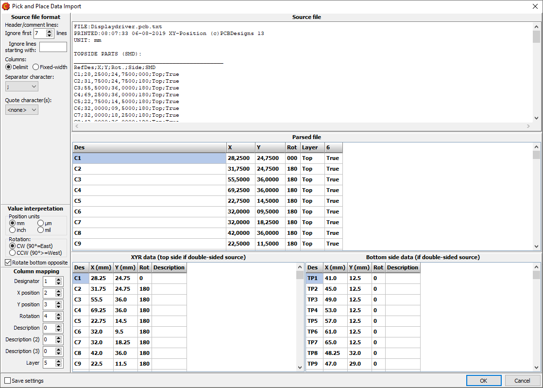
Once the data has been parsed, the components are added to the Component Top and/or Component Bottom layers.
Note: A component layer may not have duplicate component designators. When importing specifications for a component which already exists, the component properties are updated with the imported data.
If the PnP data does not have the same coordinate origin as the Gerber data, then the component symbols will be offset from their correct position on the board. This may be corrected by aligning the component data with the Gerber data.
Bill of Materials
Bill of Materials BruceA bill of materials (BOM) may be imported to a component layer from a spreadsheet or a text file. For best results, the outer contour of the PCB should be defined, and pick and place data should be imported, before importing a BOM.
When importing a text file, the file format must be specified. Choose between delimited or fixed-width fields. For delimeted fields, the delimiter character must be specified. For fixed-width fields, click on the ruler to specify the column widths. Note: Ignore the First row headers and Ignore first rows settings. These are managed in the next step.
The Import BOM dialog box is used to convert imported data to the Macaos component structure. The source data is shown in the upper grid and the parsed data is shown in the lower grid.
If the first row contains column headers, then an attempt is made to automatically link columns in the upper grid to columns in the lower grid. If necessary, specify rows in the upper grid to ignore.
The lower grid columns must be linked to their corresponding columns in the upper grid. If the column does not exist in the upper grid, then it should be mapped to column zero.
If a row contains multiple designators, then the separator character must be specified. Otherwise, this field should be left empty.
If a source column has both supplier name and supplier part number (SKU) in the same column, then the separator character should be specified. Otherwise, this field should be left empty.
If necessary, it is possible to add data to individual cells in the lower grid. Simply click on the cell and start typing to replace all text in the cell. Alternatively, click 3 times to place the cursor at the desired position in the text of the cell.
Each row in the Parsed BOM must have a unique designator. A warning is generated if empty or duplicate designator cells are found when attempting to save the imported BOM data.
Click the OK button to import the parsed BOM data.
The designator is the unique identifier for each component. For components which already exist on one of the component layers, the component’s properties are updated with the values from the imported BOM. New components are added to the left of the PCB with 10 mm spacing.
After the PCB has been published, the Assembly Data Manager module may be used to inspect and modify component data, as well as to export PnP and BOM data in various formats.
Layers
Layers BruceA printed circuit board is made up of several “layers”. These include copper layers, mask and legend layers, drill files and more. Each layer is described by one (or sometimes two) image files, and normally a file describes only one layer. The Layer overview shows the filenames and layer names of the board. The check boxes for each layer may be used to view or hide the layer in the graphic display. The rectangle to the right of the check box shows the color used to display the layer in the Graphic Display. You can right-click on this rectangle to change the color.
The Route layer is automatically generated by adding contour objects (in the Contour pane).
The controls at the top of the Layer Overview may be used to specify the number of copper layers on the board. This is automatically increased if you link additional layers in the Files pane. However, if you want to reduce the number of copper layers, you must do so here.
For single layer boards, it is not possible to link a soldermask file to the non-copper side of the board. In the Board Specifications pane, the soldermask color for the non-copper side will be set to None. Changing this to another color will indicate that the board should have soldermask on the non-copper side.
You may right-click on the layer overview to quickly show only top layers, only bottom layers, all layers or no layers.
Autolink
Autolink BruceAutolinking is a process of mapping files to the correct layers of the board. The import module is designed to support Gerber and Drill files from a wide variety of CAD system; while each CAD system has its own approach to naming its output files. In order to accommodate flexibility and accuracy, there are two different autolink strategies available: filename detection and link filters.
Use the Autolink menu to enable or disable autolinking. The menu items are:
- Autolinking off – disables autolinking
- Link by filename – enables autolinking with filename detection
- Link by filter – enables autolinking with link filters
- Create filter from current mapping – creates a link filter based on the current link status
- Link filters... - opens the link filter manager
If, during autolinking, two files appear to belong to the same layer, both files are displayed graphically and the user may choose which file to link to the layer. The other file will be left unlinked, and may be manually linked to its correct layer after autolinking has finished. This situation typically arises when there are several mechanical files and the autolinker is unable to determine which one contains the board contour.
Autolinking is usually able to map most or all of the image files properly. But it might also make wrong assumptions. The user is strongly advised to review the file mappings carefully.
Autolinking is only automatically applied the first time files are added to a product. The autolink process may be repeated by right-clicking on the file list and choosing Re-link files.
If, for some reason, a file is improperly linked during autolinking, this may be corrected by relinking the file to the correct layer.
If, during autolinking, a file has been linked to the Board layer, then an attempt will be made to automatically define the outer and inner (if any) contour objects. This operation may be disabled by selecting the Autolink|Automatically define contour (if possible) menu item, so that the check mark is removed.
Gerber Job File
Gerber Job File BruceIf the product you are importing contains a Gerber job file (*.gbrjob) then file linking information and product parameters will be extracted from the file.
Note: The final format of the Gerber job file has not yet been published. Some Gerber job files may not be compatible with the current draft specification. We will update this feature when the final format is published.
Filename detection
Filename detection BruceFilename detection analyzes all of the filenames against a set of rules in order to match each filename to its appropriate layer. Filename detection also analyzes any text files to see if they may contain the correct file mappings.
When filename detection is enabled, two additional columns are shown in the Files pane: Side and Style. The Side column shows which side of the board (Top, Bottom or Inner) that filename detection has determined the file to be. The Style column shows which type of layer has been detected. The styles are: Cu (copper), Cu out (outer layer), Cu in (inner layer), Cu in/neg (inner layer negative image), SM (solder mask), No (legend), PM (paste mask), PLT (plated through drill), NPT (unplated through drill), B/B (blind or buried drill), Rou (routing or contour), Drw (drawing), Mech (mechanical), Gold (hard gold), Glue (glue layer), Assy (assembly drawing), Peeloff (peel-off mask), and v-cut (scoring).
If the autolinker is not able to match all of the image files to a layer, then the user is given the option to try autolinking with link filters.
Link filters
Link filters BruceA link filter is a set of filename substrings, each mapped to its appropriate layer name. There are a handful of pre-defined link filters built into the import module. Users may define additional filters as needed.
The program compares all image file names with all filename substrings in all enabled link filters. It then selects the “best” filter to use when autolinking. The “best” filter is the filter having the largest number of filename matches. However, more than half of the image files must match for a filter to be considered among the best.
Link filter manager
Link filter manager BruceA Link filter is a list of filename substrings and layer names. If an image file name contains a substring from a filter, then the file will be linked to the corresponding layer.
Choose Autolink|Link filters to open the Link filter manager. There are a few built-in filters which can serve as examples when creating filters. Use the check boxes to enable filters.
To create a new Link filter:
- Click on the New button to start a new filter.
- Click in the first row of the Filename substring column, so that an edit cursor appears.
- Type in the desired substring (they are not case sensitive).
- Press Enter to complete the substring. Pressing enter again opens the next row for editing.
- For each substring, click on the text in the Stackup layer column and choose the desired layer from the menu.
- Save the filter by clicking on the Save as button and giving the filter a name.
An existing filter may be modified in the same manner and then saved with the same name (using the Save button) or as a copy with a new name (using the Save as button). Any link filters you create will be available to all users within your company.
When making a Link filter, care should be taken to use filename substrings which are unique among the image files generated by your CAD system. Check the user documentation for your CAD system, and take advantage of any output options or scripts when making a link filter.
A link filter may also be created by manually linking all of the files in a product and then executing the Autolink|Create filter from current mapping command. If drill files have been scaled, rotated and/or mirrored, these values will also be saved as a part of a filter created with this command.
Aligning drill files
Aligning drill files BruceIn principle, all Gerber and drill files should have the same coordinate origin in order to insure that all layers match. However, some CAD systems generate Gerber files separately from drill files, resulting in the two file types having different origins. This can be corrected as follows:
- Click on the Align drill with pattern button to depress the button.
- With the left mouse button, draw a selection rectangle around a drill hole. A rubber band segment stretches from the hole to the mouse pointer.
- Draw a selection rectangle around the corresponding copper pad. All drill holes move to snap onto their pads.
Aligning component or test pad data
Aligning component or test pad data BruceIn principle, all files should have the same coordinate origin in order to insure that all layers match. However, some CAD systems generate different file types with different origins. This can be corrected as follows:
- Click on the small down-arrow beside the Align button and choose Align P&P or Align test pads to enter align mode.
- With the left mouse button, draw a selection rectangle around a pick and place component symbol or test pad. A rubber band segment stretches from the symbol to the mouse pointer.
- Draw a selection rectangle around the corresponding copper pad(s) for the corresponding component or test pad. The selected symbol will move to the center of the selected pad(s). (All other component symbols will also move the same distance.)
- If necessary, press the Esc key to exit Align mode.
Note: When aligning component data, only visible component layers will be moved. If you have co0mponent data for both sides of the board, you should show or hide component layers appropriately before aligning them with the Gerber data.