Panelization
Panelization BruceThe Panelization Module creates a production-ready PCB panel from an existing PCB product. The module is used to specify the number of boards in the panel as well as the form and placement of break-off tabs. It is also possible to add fiducial marks, drill holes, a registration control coupon, bad marks, copper fill, assembly mask data and text to the frame of the panel.
Definitions
-
A single-product panel is a product where multiple instances of a single-board product are arranged in an array suitable for processing in an automated component placement system (such as a Pick-and-Place machine). The scripts in the Autopanel menu may be used to quickly generate a single-product panel. See the Automatic panelization section for more info.
-
A multi-product panel is a panel made up of several different single-board products. Multi-product panels may either be delivered as a panel or as individual boards. See the Multi-product panels section for more info.
Creating a panel
Use the following procedure to create a panel:
- Locate the product to panelize. Select the product in the Macaos Enterprise product browser and then click on the Panel button to open the panelization module.
- Run an Autopanel script (optional). If desired, select an autopanel script by clicking on the Autopanel (gears) button. After running the script, skip to step 8. See the Automatic panelization section for more info.
- Specify the array. Click on the Panelize button to create an array. Adjust the board quantity, frame width and instance spacing as desired. You can also specify scoring, corners and copper fill in the frame.
Add boards to the panel (optional). Press Ctrl+R to show the product chooser. Drag or Double-click on a product name to add it to the panel. See the Multi-product panels section for more info.
Move, rotate and flip boards (optional). Select a portion of a board outline to move or rotate the board. Right-click or press the space bar to rotate. Press Ctrl to disable snap when moving. Click to place the board or press Esc to cancel. With the mouse pointer within an unselected board, press Space to rotate 180° or Shift+Space to flip the board upside down. - Specify break-off tabs. Break-off tabs are automatically generated when panelizing a single board (if autoplace is selected). If desired, click on the Tabs toolbar button to modify the default style and placement of Break-off tabs. For a multi-product panel, break-off tabs must be added manually.
- Place fiducial marks (optional). Click on the Fiducial marks toolbar button. Specify diameters and location, and then click on the Place button.
- Place frame holes (optional). Click on the Frame holes toolbar button. Specify diameter and location of tooling holes and/or diameter, spacing and location of break-off holes, and then click on the Place button.
- Place bad marks (optional). Click on the Bad marks toolbar button. Specify the side and style of the bad marks. Specify the location of the panel mark and the board marks, and then click on the Place button.
- Place text (optional). If desired, the Text toolbar button may be used to place text, bar code or annotation fields in the frame of the panel.
- Add assembly masks (optional). Click on the Masks toolbar button. Specify the mask layer, side and fill mode; and then click on the Place button. Draw a selection rectangle around the area where the mask is to be placed.
- Add test coupons (optional). Click on the Test coupons toolbar button. Click on the Place button and then click at the location along the outer edge of the frame where you wish to place a registration control coupon. Support for IPC-2221 test coupons is under development.
- Add remarks (options). A remark is a note attached to a location on the board. Remarks give information to manufacturers, but are not visible on the final product. Click on the Remark toolbar button and then draw a circle around the location for the remark. Enter the remark text in the dialog box.
- Publish the product. Click on the Publish toolbar button to complete panel creation. Specify the product name, article number and description in the dialog box.
Graphic display
Graphic display BruceThe graphic region displays the panel. The check boxes in the layer list control which layers are visible.
See the Product browser chapter for an overview of viewer functionality such as pan and zoom, display modes, mirrored and rotated view, and measurement.
Select and place operations
Select and place operations are done with the left mouse button. The operation performed depends on the current design mode. When no operational mode is selected, selecting any portion of a board contour selects the board (for moving or copying).
Selected boards are highlighted with a white border while they are active (for movement). Once the selected board has been placed, the highlight color changes to yellow.
Rotating boards in a panel
An unselected board may be rotated 180° by pressing the Space key while the mouse pointer is within the board. This operation may be used with boards that may otherwise not be moved or rotated due to panel scoring (v-cut).
Pressing the Space key while one or more boards are selected rotates the selected board(s) by 90°.
Flipping boards in a panel
An unselected board may be flipped upside-down by pressing Shift+Space while the mouse pointer is within the board. This operation may be used with boards that may otherwise not be moved or rotated due to panel scoring (v-cut).
Flipping a board upside-down both mirrors the board and swaps top layers with bottom layers (and corresponding inner layers with each other). This feature is useful for improving copper balance or when creating a panel where the same solder paste stencil is to be used on both sides.
Layers
The layer list displays all layers in the panel. Check boxes are used to specify which layers are visible in the graphic display.
Right-click on the list to show only top layers, show only bottom layers, hide all layers or toggle layer visibility.
Right-click on a layer name to change the display color for that layer. The new color will be used throughout Macaos Enterprise.
The Help tab displays a quick reference for pan/zoom and other graphic viewer commands.
Panel properties
Panel properties BruceThe Panel design action is used to specify the quantity and spacing of board instances on the panel. Use the Panelize button to create the panel, and the Unpanelize button to “undo” the panel.
Instances (x * y): These values specify the number of boards in the X and Y directions, respectively. The total number of boards in the array is the product of the X and Y values.
Rot. 90°: If checked, the board instances will be rotated 90 degrees within the panel.
Frame: These values specify the width of the panel frame on each edge of the panel. These values are specified in millimeters.
Outer dimensions: These values show the total width and height of the panel frame. Modifying an outer dimension will automatically change the corresponding frame widths.
Instance Spacing: These values specify the distance between each instance in the array. Instance spacing may not be less than the rout width. Be sure to specify an adequate instance spacing, if you will be adding bad marks to the panel.
Rout width: This value specifies the diameter of the routing tool used to cut the slots between the boards. Use the default value (1.6mm) unless you have a specific need for a different value (such as due to thin slots or a small inner corner radius).
Scoring: If checked, scoring (V-cut) will be used between boards rather than routing along the outer X and/or Y edges.
Mixed scoring and routing
When scoring is used with non-rectangular boards, only the edges which follow the bounding rectangle will be scored. All other edges will be routed (milled). This can lead to small burrs or pointed corners at the junction between routing and scoring.
 By default, the routed slots are “locked” to stop at the scoring line, so that they will not damage neighboring boards. Slots that will cross the scoring line into waste material will do so in most cases. However the results may be unsatisfactory for slots that are not straight lines or that cross the scoring line with a small angle.
This behavior may be “unlocked,” by clicking on the padlock icon. When scoring is unlocked, the routed slots will extend at least one radius beyond the scoring line, without protecting neighboring boards.
Care should be taken when using unlocked scoring. Unlocked scoring is most suitable for symmetrical boards. In other cases, there is a risk of unwanted notches in neighboring boards.
Alternatively, you may increase the Instance spacing to be at least as large as the Rout width. This will create double scoring lines, thereby allowing the routing slots to extend beyond the scoring lines without damaging neighboring boards.
Scoring lines in the panel frame
 Scoring lines extend normally from one edge of a panel to the opposite edge. Individual scoring lines may be pulled back from the outside panel edge to the inside edge of the panel frame by holding the mouse pointer over the end of the scoring line and pressing Ctrl+V. Note: The actual scoring cut will extend a few millimeters beyond the end of the displayed scoring line, due to the diameter of the scoring saw blade. Note: Manufacturing a panel with this feature requires Jump Scoring. Not all manufacturers are able to deliver panels with Jump Scoring.
Rotating or flipping a board in a panel with scoring
It is not normally possible to select, move or rotate individual boards when scoring has been chosen. However, a board may be rotated 180° (by pressing the Space key) or flipped (by pressing Shift+Space) while the mouse pointer is within the board to be rotated/flipped.
Copper fill: The frame may be filled with copper on the outer and/or inner layer(s). Outer layers are filled with solid copper. Inner layers are filled with a pattern of 5mm diameter dots. Note: Adding copper to the outer layer increases panel stiffness, but may affect soldering temperature.
Copper fill helps increase the panel stiffness during the soldering process, and is especially useful for lead-free soldering. However, copper fill is not advised for vapor-phase soldering since the large copper mass may steal too much heat.
Corners: Choose between square, rounded or chamfered corners on the panel frame. Chamfered corners may be chosen for either top feeding or side feeding. Note: Rounded or chamfered corners are not available if the panel frame width is too small for the corner modification.
Break-off tabs
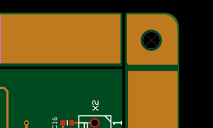
Break-off tabs BruceThe Panelization module supports two kinds of break-off tabs. Edge tabs are tabs placed along the edge of a board. Corner tabs are placed at the corner of a board.
Edge tabs may be removed by breaking, cutting or milling the tab. Milling is the safest method for removing tabs. Breaking or cutting a tab may lead to damaged solder joints, especially on surface mounted components near the break-off tab. When a corner tab is placed at the corner of all adjacent boards (i.e. not along the edge of a neighboring board) then it can be removed by drilling rather than by cutting the tab. See the Depanelization chapter for more info.
Tab length: This value specifies the length of the tabs. For edge tabs, this is the length of the narrowest point on the tab. For corner tabs, the width of the narrowest point is about 40% of the specified tab length.
Holes: A row of “mousebite” holes may be added to tabs. Diameter, spacing and offset of the holes may be specified. The number of holes is determined automatically. Mousebite holes are not added to corner tabs.
Remove soldermask: If checked, solder mask will be removed from around each break-off tab and its mousebite holes (if any). This helps prevent cracks in the solder mask when cutting the tabs. Note: Removing the solder mask may expose copper near tabs. Check all tabs carefully.
Autoplace: This function places tabs at the midpoints or corners of each board's outer contour. For boards with curved edges, the endpoints of arcs are treated as corners.
For boards with complex contours and for multi-product panels, autoplacement may give undesirable results.
Manual placement: To place tabs manually, click on the Place button (so that it is “down”).
When you click and drag the mouse pointer, a horizontal or vertical line appears. When you release the mouse button, tabs will be placed at each point where the line crosses a board edge.
Alternatively, tabs can be placed one at a time. Clicking on the edge of a board will place tabs at that position on each instance of that board in the panel. To place a tab on only one board, hold the Ctrl key down while clicking to place the tab.
For wave soldered panels, you should add at least one break-off tab to inner contours so that the material will not be removed during production.
Tab removal: To remove all tabs, click on the Clear all button.
To remove individual tabs, click on the Remove button (so that it is “down”). Left-click and draw a selection rectangle around the tab(s) to remove. All tabs at that position on all boards in the array will be removed. To remove a tab from only one board, hold the Ctrl key down while removing the tab.
Note: If a multi-product panel is specified without any tabs, the boards within the panel will be delivered as individual boards rather than as a panel. (A single-product panel may not be specified without tabs.)
Fiducial marks
Fiducial marks BruceFiducial marks consist of a copper pad and a soldermask opening. The clear zone is the size of the copper fill opening (if copper fill is enabled). A fiducial on a paste mask layer will have the same size as on the copper layer.
Fiducial marks may be added to the panel frame and/or adjacent to each board in the panel. It is not possible to place fiducial marks within the outer contour of any board in the panel.
Panel fiducial marks
Panel fiducial marks are added to the panel frame relative either to the outer corners of the frame or to the center of the panel. Typically, one would place fiducial marks near three of the panel’s four corners.
Board fiducial marks
Board fiducial marks are added to the space between boards relative to the corners or center of each board's bound box. The bound box is the rectangle defined by the board's maximum width and height. The center of a board fiducial may not be placed more than 10mm inside of the bound box. Board fiducials are typically only used for boards needing a high level of precision due to ultra-fine pitch components. It is usually sufficient with one fiducial mark per board.
Note: Board fiducials may not be placed within the contour of a board. If you need to place fiducials within a board, this should be done in the Import module prior to publishing the single-board product.
Creating fiducial marks
-
Select the desired layers, sizes and shapes for the fiducial marks.
-
Select either Panel or Boards and then select the corners (of the panel or boards) at which fiducial marks are to be placed.
-
For each direction (x or y), select Corner or Center anchoring. Then specify the distance from the corner/center of the panel to the center of the fiducial mark.
-
Click on the Place button to create the fiducial marks. Repeat as necessary.
Removing fiducial marks
To remove all fiducial marks, click on the Clear all button.
To remove individual fiducial marks, click on the Remove button (so that it is “down”) and then click on the fiducial mark to remove.
Frame holes
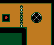
Frame holes BruceTooling holes
Tooling holes are holes typically placed near one or more corners of the panel. They are typically used for registration purposes during the manufacturing process.
Tooling holes may be defined as round holes or slots. For round holes the diameter must be specified. For slots, the slot height and width must be specified. The smaller dimension is the diameter of the cutting tool, and the larger dimension is the total length of the slot (including tool radius).
 Break-off holes
Break-off holes are a row of holes in the frame in line with an edge of the boards in the panel. These are used to break away portions of the frame when removing the finished boards from the panel.
Creating holes
-
For tooling holes, select a shape and specify the hole dimensions. Select the panel corners at which tooling holes are to be placed. For each direction (x or y), select Corner or Center anchoring. Then specify the distance from the corner/center of the panel to the center of the hole or slot. Note: Remove all corner check marks if you only wish to create break-off holes.
-
For break-off holes specify a diameter and spacing. Select which edge(s) of boards the break-off holes should follow. Note: Remove all edge check marks if you only wish to create tooling holes.
-
Click on the Place button to create the holes. Repeat as necessary.
Removing holes
To remove all tooling holes and break-off holes, click on the Clear all button.
To remove individual tooling holes or break-off holes, click on the Remove button (so that it is “down”) and then draw a selection rectangle around the hole(s) to remove.
Text and bar codes
Text and bar codes BruceYou may add text, bar codes or annotation fields to the panel frame.
Plain text on the legend layer may also be placed within individual boards, which is useful when giving the boards in the panel individual position identifiers.
Select a target layer, and enter the text to place.
Plain text
The Font height specifies the height of the characters. Select a Rotation, if desired. Text on a bottom layer will automatically be mirrored.
Click on the Place button (so that it is “down”) and then click where you wish to place the text. Text may only be placed where it will fit within the frame of the panel (or, on Legend layers, within the board).
To remove text, click on the Remove button (so that it is “down”) and then click on the text to remove.
Bar code
A bar code may be placed on either legend layer of the panel frame. The bar code is generated in either Code128-B or Data Matrix ECC 200 format.
White legend on green solder mask will give an inverse bar code image. Note: Many bar code reader apps do not support inverse images. We recommend the “ScanLife” app by Scanbuy, Inc., available at www.getscanlife.com.
If a Code 128-B bar code is to be placed along one of the vertical edges of the frame, then check Vertical orientation. A bar code on the bottom layer will automatically be mirrored.
Click on the Place button (so that it is “down”). Then click where you wish to place the bar code. A bar code may only be placed where it will fit within the frame of the panel. It is not possible to place a bar code on the boards.
To remove bar codes, click on the Clear all button. All bar codes will be removed.
Note: The bar codes are limited to ASCII characters from 32 to 127. This includes all digits, all letters in the English alphabet, and many symbols. Non-English characters or characters with accents or other diacritical marks are not supported.
Annotation field
An annotation field is a solid rectangle which may be used for laser etching, handwritten serial numbers or other information. It may be placed on a legend or solder mask layer of the panel frame.
Note: If you need to place an annotation field within the boards of the panel, this can be done with the Assembly masks design action.
Click on the desired layer name in the layer list, and then click on the Place button (so that it is “down”). Choose whether the annotation field is to be drawn or placed with a defined mark size.
If drawn, then draw a rectangle defining the size of the annotation field.
If placed with a defined mark size, click first on the Define button. This opens a dialog box for calculating the appropriate size for a text or bar code. You should enter a text similar (and with the same number of characters) as will be actually used. After closing the dialog box, place the annotation field as desired.
Note: For laser engraved 2-dimensional bar codes, we recommend a module size of 0.5 mm or larger.
Note: Two-dimensional bar codes use different encodings for a text with numbers-only, English alphanumeric text, or containing other-language characters. The actual bar code may differ in size from the sample displayed in the dialog if the sample text differs in number of character types.
To remove annotation fields, click on the Remove button (so that it is “down”) and then click on the fields to remove.
Bad marks
Bad marks BruceBad marks are locations (either bare copper or legend ink) on a panel where an indicator may be placed to mark boards or panels that should be ignored in the assembly process. The bad boards or panels may be marked with a felt marker or a sticker. Many assembly machines are capable of detecting bad marks, and will automatically skip the bad boards/panels during assembly.
-
Specify the side, style, diameter and shape of the bad marks.
-
Specify the location of the mark for the panel. The position is specified as the distance from the corner, so the values will always be positive.
-
Specify the location of the marks for each board. The position is specified relative to the selected corner. For bottom or left sides, it may be necessary to specify a negative value to place the mark outside of the board.
-
Click on the Place button to place the specified bad marks.
Be sure to check that the bad marks for each board do not get placed within neighboring boards. If necessary, you should increase the instance spacing between the boards to make room for the bad marks.
Removing bad marks
To remove bad marks, click on the Clear all button. All bad marks will be removed.
Assembly masks
Assembly masks BruceOften, the necessary data for assembly masks is missing from the Gerber files created by the board designer. Especially in cases where assembly is being done by an EMS provider, this missing data can be a problem. It is the EMS provider who knows the processes and needs to specify the masks, but getting this information to the board designer early enough to be included in the design is usually not possible. With the assembly masks feature, the mask areas may be specified by the production engineer while creating the assembly panel.
Masks are specified by drawing rectangles on the panel. The Fill mode determines whether the mask will be applied to the entire rectangle or to all soldermask openings within the rectangle. This is repeated at the same location on all instances of the same board in the panel.
The following assembly masks (top or bottom side) may be defined:
-
Peel-off mask (Blue mask): Used to protect a region from the solder process(es). Normally applied to an entire rectangle.
-
Paste mask: Defines openings in a solder mask stencil. This data may then be used in the Stencil Module to create a stencil product. Normally applied to pads within the rectangle.
-
Glue mask: Defines openings in a glue mask stencil. Normally applied to an entire rectangle drawn between the pads of a component.
-
Hard gold: Defines which pads should have a hard (electrolytic) gold (finger contact) finish. Normally applied to pads within the rectangle.
-
Carbon print: Defines which pads should have a carbon (finger contact) finish. Normally applied to pads within the rectangle.
-
Kapton tape: Used to protect a region from chemical or solder processes. Normally applied to an entire rectangle.
-
Legend: The notation layer, sometimes also called silkscreen. Used to create an annotation field.
-
Solder: The solder mask layer. Useful for removing solder mask from a region, in order to help prevent cracks in the solder mask when manually cut or otherwise mechanically processed. Note: Care should be taken to avoid inadvertently exposing copper.
A mask is defined by the chosen fill mode when a selection rectangle is drawn. The fill modes are:
-
Duplicate pads: The mask duplicates all soldermask openings within the selection rectangle. This mode is normally used for paste mask, hard gold and carbon layers. The mask will normally be somewhat larger than the copper pad it covers, but this should not be a problem. For a paste mask, the actual stencil opening size may be adjusted to a percentage of the copper pad size in the Solder paste stencils module. For hard gold and carbon layers, the mask is simply used to document to the manufacturer which pads should have a hard gold or carbon finish.
-
Rectangle: The mask covers the entire area within the selection rectangles. This mode is normally used for peel-off and glue mask layers.
Note: For the Legend layer, you choose a placement method rather than a fill mode. This is the same as for placing an annotation field. You should avoid placing an annotation field over copper traces if the annotation text will be laser engraved (due to the possibility of etching through the solder mask).
Note: Assembly masks are added to the panel, and not to the boards within the panel. For this reason, if a board is moved or rotated, any assembly mask modifications you have created will not follow the board.
To remove all mask objects, click on the Clear all masks button.
To remove individual mask objects, click on the Remove button (so that it is “down”) and then draw a selection rectangle around the mask object(s) to remove.
Test coupons
Test coupons BruceRegistration control coupon
A registration control coupon may be added to the panel frame by clicking the Place button (so that it is “down”) and then clicking at the desired location. The coupon has a combination of thin (0.1 to 0.175 mm) lines and plated holes, for use with cross-section or registration testing of the finished panel. The product number is encoded as a Data Matrix at either end of the coupon.
To remove all registration coupons, click on the Remove button.
Note: If the stackup has copper layers with a copper thickness of more than than 35µm (1 oz) then the lines in the registration coupon are enlarged accordingly.
Impedance coupons
To add an IPC-2221B compliant type Z impedance control coupon to the panel frame, do the following:
- Select a signal style. A signal may be above, below or between copper planes. A signal may be either single-ended or differential. It is also possible to specify a broadside-coupled differential signal (with parallel signals on adjacent layers).
- Select a signal layer. This is the layer for the signal trace, or for the upper signal trace when broadside-coupled.
- Specify the width (and spacing for edge-couple differential pairs) of the signal trace(s).
- Click on the Add to coupon button.
- If desired, repeat steps 1-4 for addition impedance-critical signal configurations. The test coupon may have up to 12 signal configurations, but no more than 2 configurations on each layer.
- If necessary, right-click on the signal list to remove a signal configuration from the list.
- Click on the Place button (so that it is “down”) and then click at the desired location.
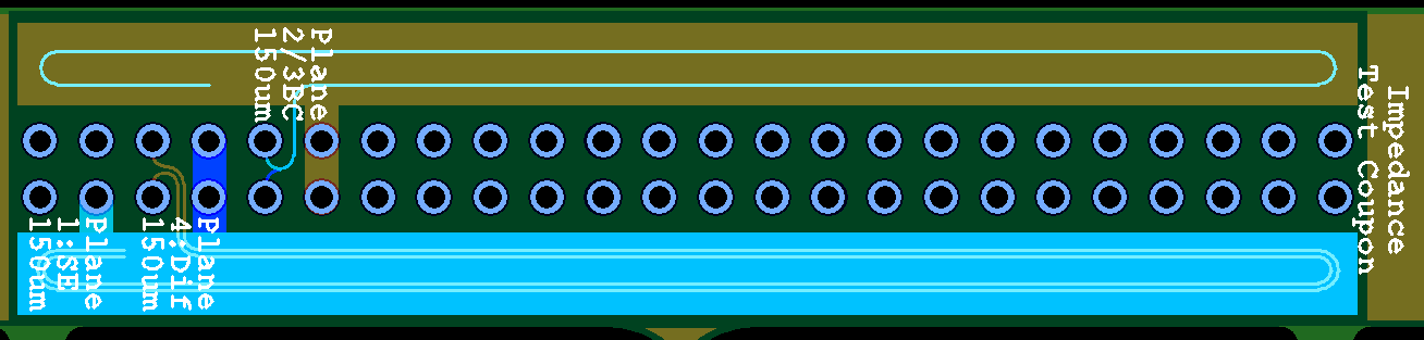
The resulting test coupon has signal traces and planes in accordance with the type Z coupon specification. If the panel has a legend top layer, then the terminal pads are annotated to indicate the signal type and layer.
If possible, signal configurations will be placed only on one side of the coupon, allowing it to fit into a 10 mm frame margin. If both sides are used then the frame margin must be at least 14.5 mm.
Board as coupon
Any single-board product may be added to the panel frame as a coupon. The selected board must be small enough to fit in the panel frame. All (non-routing) layers in the coupon which also exist in the panel are copied to the desired location of panel frame.
To add a board as coupon, do the following:
- Click on the Place button. This opens the Panel coupon chooser dialog box.
- The dialog box lists all products with a height or width less than the specified maximum size. If desired, you may specify a different maximum size and then click the Refresh list button to update the chooser list. Select the desired coupon product and then click the OK button to load the product into the panel module.
- The coupon outline shows as a floating rectangle which follows the mouse pointer. If desired, press the Space key to rotate the coupon 90 degrees counter-clockwise. Click at the desired location(s) for the coupon.
- Once the coupon has been placed, click on the Place button again to exit placement mode.
Note: You may not place a coupon such that it would extend outside of the panel or within any of the boards in the panel.
Graphical remarks
Graphical remarks BruceYou may add remarks to a panel. This is useful, for example, if there is some information about a specific region on the board which needs to be communicated to the manufacturer. To place a remark:
-
Use the Actions|Add remark command to activate the graphical remarks mode.
-
Draw a circle around the area on the board to which the remark applies.
-
Enter the text of the remark in the Place remark dialog box. Add line breaks as appropriate. The text will be placed to the right of the circle.
-
Click OK to complete creation of the remark.
Use the Actions|Delete remarks command to remove all remarks from the board.
Automatic panelization
Automatic panelization BruceA single product may be panelized automatically with a script. An autopanel script automatically generates a panel by fitting the appropriate number of boards into the panel and adding fiducial marks, tooling holes, etc as specified in the script. In most cases, a finished panel can be generated with one click!
The MacaosDemo script is supplied with Macaos Enterprise. This script will create a panel approximately 250 mm by 150 mm with 10 mm frame borders, four tooling holes and three fiducial marks. To modify this script or create additional scripts, use the Configure|Script manager command to open the Autopanel script manager.
The available scripts are listed in the left column. Clicking on a script name loads the selected script so that its properties may be viewed or modified. These properties include:
Script style: Choose the style of script
- Best fit: A best fit script fits as many boards as possible into a panel between the specified minimum and maximum panel size. The panel frame size remains constant.
- Fixed size: A fixed size script fits as many boards as possible into a panel with the specified panel size. The panel frame size is adjusted as necessary.
- Frame objects only: A frame objects script adds frame objects to an existing panel, leaving the panel size and frame size unchanged.
Panel size: The minimum, ideal and maximum panel size. The script will find the instance combination that is closest to the ideal panel size, without exceeding the min/max limits. If Do not rotate boards in panel is not checked, then the script will rotate all boards by 90 degrees if that will increase the number of boards that will fit in the panel.
Panel properties: Use these properties to specify the frame width, spacing, corners and other parameters of the panel.
Break-off tabs: Use these properties to specify the size and placement of break-off tabs in the panel. If neither of the autoplace options are selected, then no tabs will be added to the panel by the script.
Objects in panel frame: A list of the optional objects that will be added to the panel frame by the script. There are five types of objects:
-
Fiducial marks: Any number of fiducial mark definitions may be added to the script
-
Tooling holes: Any number of tooling hole definitions may be added to the script
-
Annotation field: Any number of annotation fields may be added to the script
-
Break-off holes: Only one definition for break-off holes may be added to the script
-
Bad marks: Only one definition for bad marks may be added to the script
-
Text or bar code: Any number of text or bar code objects may be added to the script.
Click on the Add button to create a frame object definition. If a frame object in the list is selected when clicking the Add button, then a copy of that object will be created. Otherwise, a list is displayed from which you choose which type of object to create. After specifying all parameters, click on the Save button to save the object definition to the script.
When specifying a text or bar code object, right-click on the text field to insert a product property as the text.
It is not possible to include assembly mask or test coupon objects in a script. These must be added to the panel by the user after the script has been run.
Use the buttons at the bottom of the script list to save scripts. Right-click in the scripts list to delete, rename, import or export a script.
Scripts are stored together with the user's program settings. To share a script with another user, export the script to a file and send the file to the other user for import into their script manager.
There are also scripts available for download at www.macaos.com/support/panelscripts.
Multi-product panels
Multi-product panels BruceA multi-product panel may be easily created by simply choosing compatible products from the product chooser and placing them at the desired location in the panel.
Product chooser
The Product chooser works in a similar manner to the Macaos Enterprise Product Browser. It lists folders and products which are compatible with the panel's initial product.
The # column lists the quantity of each product in the panel. For a detailed view of a product or its specifications, right-click on the product and choose View product details to open the product viewer
Check boxes at the bottom of the product chooser are used to specify how strictly the products are checked for compatibility.
-
Match stackup: If checked, then only products having the same buildup will be listed. Otherwise, all products with the same number of layers will be listed.
-
Match colors: If checked, then only products having the same surface finish, soldermask color and legend color will be listed. Otherwise, products will be listed regardless of surface finish or color.
By default, the product chooser is hidden, since it uses valuable graphic display space. Use the Configure|Product chooser menu command or press Ctrl+R to show or hide the chooser.
Panel properties for multi-product panels
A multi-product panel may be manufactured either as a panel or as individual boards, as specified with the Manufacture as radio buttons. When individual boards is selected, there is no frame and there should be no break-off tabs between the boards. When panel is selected, the panel frame and corners may be freely specified. Each board in the panel should have break-off tabs on at least 3 sides.
Due to the complexities that can arise with many different products on a panel, there are limitations on some of the panel properties. The route width must be specified prior to adding a product to the panel. Instance spacing is ignored, since boards are placed manually.
Scoring may only be added in cases where all boards in a row (or column) have the same height (or width). It is not possible to select or move boards once scoring has been specified. Therefore, all boards should be placed prior to selecting X-scoring or Y-scoring. After scoring has been chosen, a board may be rotated 180° by pressing the Space key while the mouse pointer is within the board to be rotated.
Working with multi-product panels
A board may be added to a panel by either dragging the product from the list into the graphic display, or by double-clicking on the product in the list. The new board becomes the active board and is highlighted with a white border.
Note: It may take some time to download the graphic data for the product you are adding to the panel, so after dropping a new product into a panel, you may need wait until the data is loaded before you can move and place the board.
The active board follows the mouse pointer until it has been placed. The Panelization module has a snap function that prevents you from moving a board over an already placed board or frame object. It also snaps the edges of the active board to align with edges of placed boards. This may lead to some confusion when you first bring a new product into a panel, since the board may seem to be locked outside of the panel. The easiest solution is to simply place the board where it is, and then after the panel (and zoom) automatically resize themselves, you can move the new board to where you want it to be placed.
While a board is active (white border), the following operations may be performed:
- Space Pressing the space bar rotates the board 90 degrees around the mouse pointer.
- Shift Pressing Ctrl deactivates the auto-snap functionality as long as Ctrl is depressed.
- Left-click Clicking the left mouse button places the board at the current position.
- Del Pressing Del deletes the board from the panel.
- Esc Pressing Esc aborts the current operation. For a new board, the board is deleted. For an existing board, it is returned to its previous position.
- Right-click Clicking the right mouse button aborts the current operation.
To make a different board (or boards) active, draw a selection rectangle around any portion of the board's outline. To add a new copy of an existing board to the panel, press the Ctrl key while making the board active.
Each time a board is placed, the panel is resized using the frame widths specified on the Panel Properties page. The panel size and area are shown in the bottom left corner of the window.
A board may be rotated 180° or flipped top/bottom in its position by pressing Space (rotate) or Shift+Space (flip) while the mouse pointer is within the board.
When viewing a multi-product panel, an additional Product number layer shows the placement and product number of each board in the panel. This layer is for documentation purposes only and may not be exported as a manufacturing layer.
The status bar at the bottom of the graphic display shows information about the active board. This information includes the product number, board size, rotation and number of break-off tabs.
Note: All boards should be placed in their final positions prior to placing tabs, holes, text, etc.
Publishing a panel
Publishing a panel BruceOnce everything has been specified, the product may be published to the Macaos server. After specifying the product name, article number and description in the dialog box, a product number will be assigned and the product files will be uploaded to the server.
While publishing, a panel drawing and a stackup drawing for the product are generated in PDF format. The user will have the opportunity to specify options and title block text for each drawing. These drawings are available from the Macaos Enterprise Product Browser.
Once the product has been published, it will be visible in the Never Ordered and Recently Published folders of the Macaos Enterprise Product Browser, for pricing and order placement.
Panel drawing
A panel drawing, in PDF format, may be generated for the current panel configuration. The drawing shows the locations and x/y coordinates of each board on the panel, as well as each drill hole, fiducial mark and bad mark.
Before generating the panel drawing, it is possible to specify text for the various fields of the drawing's title block.
There are two options available when generating a panel drawing:
Add dimension lines to panel drawing: If selected, then the drawing will include dimension lines showing the locations of fiducials, tooling holes, bad marks, etc. Dimension lines for the panel size are always included in the drawing.
Include slots and break-off tabs in panel drawing: If selected, then break-off tab holes and the outlines of all routed slots are drawn. If not selected, then only the board outlines are drawn.
The panel drawing is also included with the product files when the panel is published, and is therefore available from the Macaos Enterprise Product Browser.