Macaos Gallery 2.3 (October 2020)
Macaos Gallery 2.3 (October 2020) BruceAssembly Data Manager (ADM)
The new Macaos ADM is an integrated BOM Tool and Pick and Place Data Manager for PCBs. It provides an environment for managing and reviewing Pick and Place (PnP) and Bill of Materials (BOM) data.
Note: This module is only available in the EMS version of Macaos Gallery.
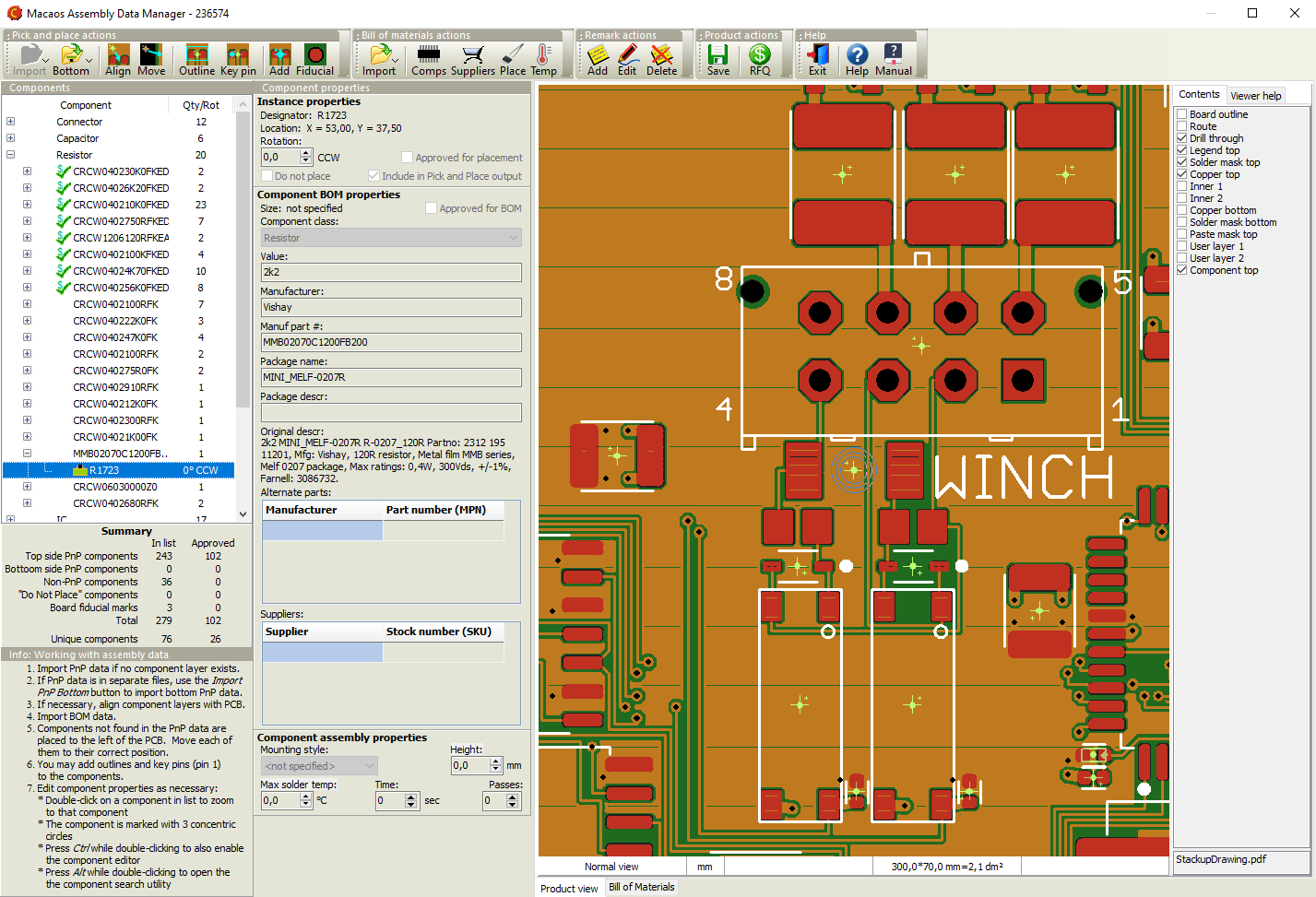
The ADM helps dramatically reduce time and effort in preparing assembly data, by combining the following features in a single module:
- Graphic viewer with component editing functionality
- Structured component overview with properties editor
- Component search facility
- Component price estimator
- Component rotation, height and solder temperature editor
- Export PnP and BOM data
The ADM makes use of the recently released X3 extensions1 to the Gerber Format to combine PnP, BOM and Assembly Drawing data into an integrated component layer of a PCB product. As CAD systems2 implement these extensions, a rapid and error-resistant path from designer to manufacturer may be achieved.
The component layer displays the location, rotation, size and key pin location of each component together with properties such as manufacturer part number, supplier SKUs, height, max solder temperature, etc. The use of a standards-based structure for this information allows purchasers, supplers, process line operators, etc to automate their systems and thereby reduce costs.
1 Macaos actively participates in the development of these standards.
2 Some CAD systems, such as kicad, already support Gerber X3 output.
See the ADM user guide for more info.
Note: The ADM is not included with Macaos Gallery Pro.
Simple PCB Editor
With the Simple PCB Editor, it is possible to make certain adjustments to a PCB product. You can:
- Change the diameter of a contour tool or drill tool
- Toggle the plating of a drill tool’s holes
- Change the extent (depth) of a drill layer
- Reassign (swap) or change the polarity of copper layers
- Change the via protection style of a via protection layer
- Replace a layer with the contents of a Gerber file
Right-click on a single-board PCB product (in the Product Browser) to open the Simple PCB Editor.
Stencil module improvements
The stencil module now calculates the Aspect ratio and Area ratio for the smallest apertures in the stencil. This is used to recommend a maximum stencil thickness when creating a stencil. See Stencil ratios for more info.
DXF file import
Limited support for importing DXF files has been added. A DXF file may be imported to a user layer in the Import module. When loading a file directly in the Stencil module, you may load either a Gerber file or a DXF file.
Only those DXF entities which easily map to Gerber-style objects are imported. Other entities are ignored. For more info see DXF Files.