Tooling holes
Tooling holes are holes typically placed near one or more corners of the panel. They are typically used for registration purposes during the manufacturing process.
Tooling holes may be defined as round holes or slots. For round holes the diameter must be specified. For slots, the slot height and width must be specified. The smaller dimension is the diameter of the cutting tool, and the larger dimension is the total length of the slot (including tool radius).
 Break-off holes
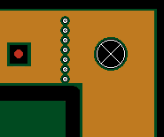
Break-off holes are a row of holes in the frame in line with an edge of the boards in the panel. These are used to break away portions of the frame when removing the finished boards from the panel.
Creating holes
-
For tooling holes, select a shape and specify the hole dimensions. Select the panel corners at which tooling holes are to be placed. For each direction (x or y), select Corner or Center anchoring. Then specify the distance from the corner/center of the panel to the center of the hole or slot. Note: Remove all corner check marks if you only wish to create break-off holes.
-
For break-off holes specify a diameter and spacing. Select which edge(s) of boards the break-off holes should follow. Note: Remove all edge check marks if you only wish to create tooling holes.
-
Click on the Place button to create the holes. Repeat as necessary.
Removing holes
To remove all tooling holes and break-off holes, click on the Clear all button.
To remove individual tooling holes or break-off holes, click on the Remove button (so that it is “down”) and then draw a selection rectangle around the hole(s) to remove.